Cisco Press

As Secure Socket Layer (SSL) Virtual Private Network (VPN) technology has become more mature and has rapidly been deployed over recent years, it has gained the attention of network and IT administrators who are looking for remote access VPN solutions that provide ubiquitous access and low-cost deployment and management. At present, no official standards exist for SSL VPN technologies; various vendors use different implementations. This chapter takes a close look at the evolution of the SSL VPN technology to help you understand how this technology works.
Cryptographic Building Blocks of SSL VPNs
A VPN carries private traffic over public networks. A secure VPN meets the following basic requirements:
Authentication guarantees that the VPN entity communicates with the intended party. The authentication can apply to either a VPN device or a VPN user. For example, in a remote access VPN, the VPN head-end device can authenticate the user PC to make sure that it is indeed the PC that owns the IP address that it uses to connect to the concentrator. The concentrator can also authenticate the end user who is using the PC to properly assign user privileges based on the user’s information.
Confidentiality ensures the data’s privacy by encrypting the data.
Message integrity guarantees that the data’s content has not been modified during the transmission.
The following sections examine how these requirements are fulfilled through the use of various cryptographic algorithms. Readers who are already familiar with these cryptographic algorithms can skip these sections and move directly to the SSL section.
Hashing and Message Integrity Authentication
The following sections describe hashing and its use in cryptography.
Hashing
Hashing plays an important role in a security system by ensuring the integrity of the transmitted message. A hashing algorithm converts a variable-length text field into a fixed-size string. Hashing algorithms used in a security system have the following two properties:
One-way hashing mechanism: This means that given the hash output, it is difficult to invert the hashing function to get the original message.
Collision-free output: This means that for a hashing algorithm, it is computationally infeasible to find any two messages that have the same hash output.
Because of these properties, a hash is also known as a message digest or digital fingerprint. People can generate a small hash output from a large document and use the hash output as the digital fingerprint of the document. This digital fingerprint can then be used to ensure that the message has not been tampered with during its transmission over an insecure channel. In addition, from the digital fingerprint, it is impossible to reveal the content of the original message.
Up to now, the most commonly used cryptographic hash algorithms have been message digest algorithm 5 (MD5) and Secure Hash Algorithm 1 (SHA-1). Both of these have been considered one-way and strongly collision-free hashing algorithms. MD5 provides 128-bit output, and SHA-1 provides 160-bit output. Because of its larger size, SHA-1 is normally considered more secure, but computationally more expensive, than MD5. With hardware and software implementation in today’s networks, the performance difference is usually not a concern. Therefore, SHA-1 is the preferred hashing algorithm for use in a VPN deployment.
Message Authentication Code
Message authentication code (MAC) is a cryptographic checksum that is used to ensure the integrity of the message during transmission. To generate a MAC, you can use either an encryption algorithm, such as Data Encryption Standard (DES), or a hashing algorithm. Hashing is generally much faster than encryption algorithms, so the hash-based MAC (HMAC) is the most popular way. HMAC is a keyed hash function. Here is how it works: To generate an HMAC of a message M, you need to pick two system parameters, a hashing function H (normally MD5 or SHA-1) and a key K. The HMAC of the message is calculated as follows:
HMAC(K,M) = H(K XOR opad,H (K XOR ipad,M))
where opad is the string 0X5c and ipad is the string 0x36.
In a crypto system, the key K used here is normally generated during the key negotiation and establishment process between the two peers. Note that the two-level hash makes an HMAC function much more secure than a simple keyed hash function.
Figure 2-1 illustrates how HMAC functions between the sender and recipient of the message.

HMAC
The Security of MD5 and SHA-1 – Recent research conducted by a group of Chinese cryptographers, including Xiaoyun Wang, has shown that MD5 and SHA-1 are not collision free, and algorithms have been developed to find collisions faster than using brute force. For example, SHA-1 has a 160-bit output, so if you hash 280 random messages, you will find one pair of messages that have the same hash output. Three Chinese cryptographers proved that they can find collisions in SHA-1 with 269 operations, which is 2000 times faster than using brute force.
The implications of these findings are described by Bruce Schneier at his web blog (https://www.schneier.com/blog/archives/2005/02/cryptanalysis_o.html) and by Eric Rescorla at https://www.rtfm.com/movabletype/archives/2004_08.html#001059.
Here is a brief summary:
The attack threatens the nonrepudiation property provided by hashing algorithms in digital certificates.
It is believed that HMAC is still secure against this attack.
The current attack is on the far edge of feasibility with current technology.
These findings push industry toward developing more secure hash algorithms such as SHA-256 or other crypto methods. More details on SHA-2 can be found at https://en.wikipedia.org/wiki/SHA-2.
Encryption
Encryption algorithms transfer plain text into cipher text. Different from hashing, encryption algorithms require keys for encryption and decryption. Two main types of encryption algorithms exist:
Symmetric encryption: Uses the same key for encryption and decryption. It is also known as secret-key cryptography. The symmetric algorithms are normally used to encrypt the content of a message. Two main types of symmetric encryption algorithms exist:
— Stream ciphers, such as RC4
— Block ciphers, such as DES, Triple DES (3DES), and Advanced Encryption Standard (AES)
Asymmetric encryption: Uses different keys for encryption and decryption. Asymmetric encryption is also known as public-key cryptography. An asymmetric encryption system consists of two computationally associated keys. One, known to the public domain, is called the public key; the other is known only to the owner of the key pair. Depending on the use of the public and private key pairs, asymmetric algorithms can be used for either encryption or authentication purposes. Figure 2-2 illustrates the usage of asymmetric algorithms. Consider the example of Alice and Bob, who want to use asymmetric algorithms for secure communications. For encryption purposes, Alice would encrypt the message using Bob’s public key and send the cipher text to Bob. Upon receiving the cipher text, Bob, who is the only owner of the corresponding private key, can then decrypt the message with his private key. For authentication purposes, Alice would encrypt (or sign) the message using her own private key. Other people such as Bob can then verify the authenticity of the message by using Alice’s public key, which is the only key that matches the signing private key. The real-world use of asymmetric algorithms in crypto systems involves other components. We discuss them in the next few sections.
Because symmetric algorithms are much faster than asymmetric algorithms, digital certification or key management is more commonly used for data encryption than asymmetric algorithms. The popular examples of asymmetric algorithms are Diffie-Hellman (DH) algorithms and Rivest, Shamir, and Adelman (RSA).
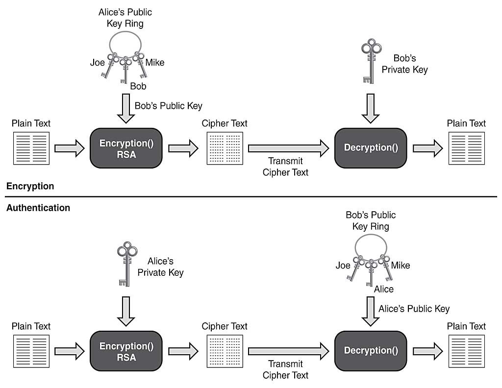
Applications of Asymmetric Algorithms
RC4
Designed by Ron Rivest in 1987 for RSA Security, RC4 is the mostly widely used stream cipher. Because of its speed and simplicity, RC4 has been deployed in many applications, such as the SSL Protocol and the Wired Equivalent Privacy (WEP) Protocol, which are used to secure wireless network traffic.
As a stream cipher, RC4 works on bits of plain-text data and encrypts them one at a time by XORing the keystream with the plain text. The keystream is generated by passing the encryption key and initialization vector (IV) through a pseudorandom number generator.
For SSL, most web browsers support RC4 encryption with two different key sizes: RC4-40bit and RC4-128bit. Newer browsers, such as Internet Explorer 7.0 and Firefox, have started to support stronger ciphers such as AES.
DES and 3DES
Data Encryption Standard (DES) is by far the most widely used symmetric encryption algorithm. DES is a 64-bit block cipher that works on an 8-byte data block. The output cipher block has the same 8-byte length. At the decryption side, the same algorithm is applied in reverse with the same key. Due to the requirement of having parity bits, the effective key strength of DES is 56 bits.
To encrypt a message that exceeds the DES block size, the individual cipher blocks are chained using a certain mode of operations. There are various modes of operations, such as Electric Code Book (ECB), cipher block chaining (CBC), and so on. The CBC mode is the commonly used mode of operation in commercial implementations. In CBC mode, each block of cipher text is XORed with the next plain-text block to be encrypted, thus making all the blocks dependent on all the previous blocks. The first block of data is XORed with the IV. The CBC mode adds more security compared to the ECB mode because of its extra XOR steps.
Since its design by IBM in 1970s, the DES algorithm has withheld aggressive cryptoanalysis over the years. However, its 56-bit key length is too short, and it has become weak over the years with the rapidly increasing computational power of consumer-grade systems.
3DES addresses DES’s insufficient key length problem. 3DES performs DES three times with three sets of keys for a total of a 168-bit key length. To perform 3DES, the popular operation is to Encrypt-Decrypt-Encrypt (EDE). That is, DES encrypts the message using key 1, decrypts the message using key 2, and finally, encrypts the message using key 3.
AES is one of the cipher options for SSL v3 and Transport Layer Security (TLS).
AES
To replace the aging DES standard, the National Institute of Standards and Technology (NIST) called for the submission of an Advanced Encryption Standard (AES) in 1997. Out of several candidates such as MARS, Twofish, Serpent, Rijndael, and RC6, Rijndael was chosen as the final standard.
AES is also a block cipher that works on a 128-bit data block and has a key size of 128, 192, and 256 bits. More information on AES can be found at: https://en.wikipedia.org/wiki/Advanced_Encryption_Standard.
As a new federal standard and one that is less computationally intensive and cryptographically stronger than 3DES, AES has been rapidly added in vendors’ implementations and deployed in VPN networks. Currently, many vendors also support AES hardware acceleration. AES is one of the cipher options for SSL v3 and TLS.
Diffie-Hellman
Published in 1976, Diffie-Hellman (DH) was the first published public-key algorithm. Diffie-Hellman is a key agreement protocol that enables communication parties to agree on a shared secret without any prior-known secrets. Diffie-Hellman is often used in key exchange and during the establishment phase of a VPN tunnel. The Diffie-Hellman algorithm works as follows:
The communication parties agree on two system parameters: a large prime p and a generator g. These are chosen such that for any value V < p, there exists a value w so that gw mod p = V. With this requirement, g can be used to generate all the numbers from 1 to p–1.
Each communication party, say X and Y, generates a private key, x and y, each of which is a random number smaller than p. To calculate the corresponding public keys, Xx and Yy, the following formulas are used:
— Public key for party X: Xx = gx mod p
— Public key for party Y: Yy = gy mod p
The two communication parties then exchange the public key over the insecure channel. Upon receiving the other side’s DH public key, each party calculates the shared secret (SS) using the following formulas:
Party X: SS = (Yy)x mod p = gyx mod p
Party Y: SS = (Xx)y mod p = gxy mod p
Both parties come up with the same common secret.
The DH parties must share the system parameters p and g, which are called DH group parameters. The following are several common DH groups with a different p:
Group 1: 768-bit modulus
Group 2: 1024-bit modulus
Group 5: 1536-bit modulus
Note that during the DH public key exchange process, no authentication process is defined. This ensures that the communication parties are getting the right public key from the intended party. Thus, DH is vulnerable to a man-in-the-middle attack, in which an attacker can intercept the communication channel and spoof the identity of the communication parties to perform DH exchange with party X and Y, respectively. Thus, the attacker establishes two shared secrets with X and Y separately, and can use these shared secrets to intercept further communication between the two communication parties protected by the DH secrets. An authenticated DH exchange mitigates this vulnerability.
Well-known uses of DH algorithms are key exchange and perfect forward secrecy in the Internet Key Exchange (IKE) Protocol, the key exchange protocol for IPsec VPN and the key exchange in the TLS protocol.
RSA and DSA
RSA and DSA are the two most common public key algorithms used in digital signature applications. RSA was designed by Ron Rivest, Adi Shamir, and Len Adelman (hence RSA) in 1977. Different from the Diffie-Hellman algorithm, the RSA algorithm is based on the fact that no efficient way exists to factor very large numbers. The common key size is 512-bit, 1024-bit, and 2048-bit. The performance of RSA is much slower than secret key algorithms such as DES. So RSA is normally not used for bulk data encryption. It is used mainly in digital signatures to “sign” the digital signature or in digital enveloping to encrypt a secret key that is used to encrypt the data.
In 1991, NIST proposed that the Digital Signature Algorithm (DSA) be used for applications that require digital signatures. It was standardized as the Digital Signature Standard (DSS) by the United States federal government standard for digital signatures.
Digital Signatures and Digital Certification
Authentication and integrity are important properties for secure VPNs. These include entity authentication, data origin authentication, integrity, and nonrepudiation. Digital signatures and certificates provide a scalable trust system. The following sections describe the digital signatures that provide the security properties and digital certification described in the preceding section.
Digital Signatures
In a secure communication, you must often ensure that a message comes from an authentic sender, not from malicious parties who spoof and claim that they are the intended sender. On the flip side, you might also require that the sender of the message cannot later deny being the source of the message (this is known as nonrepudiation). People sign paper documents and use the signatures as proof of authenticity and nonrepudiation. In the digital world, digital signatures (through digital signing) are designed for exactly the same purpose.
Digital signing refers to the action of encrypting the hash of the message by using the sender’s own private keys. The output is called a digital signature. From the knowledge you have gained in the previous sections, it is not hard to see why the term digital signature is used: The hash of the message generates an easy-to-calculate, one-way digital fingerprint of the message. Signing using a private key guarantees the authenticity of the source of the message, because only the person who signs the message has the private key. The signature can be easily verified by using the corresponding public key that is posted in the public domain.
Figure 2-3 illustrates the signature verification process. Essentially, the recipient of the message with the corresponding signature performs two calculations: decryption of the received signatures using the sender’s public key to get the hash and calculation of the hash using the received message. After these two actions are completed, the recipient compares the two outputs. If they are the same, the recipient verifies the signatures to be authentic.
Figure 2-3
Digital Signature Verification
The common digital signature algorithms are RSA with MD5 or SHA-1 and DSS with SHA-1.
Public Key Infrastructure, Digital Certificates, and Certification
The preceding section showed how you can use digital signatures to achieve important security requirements, such as entity authentication, nonrepudiation, and data origin authentication. You might have noticed that one piece is still missing in the picture. To verify the digital signature, you need to have the sender’s public key. This public key should be distributed not only to the public in a scalable way but also be trusted as the true public key of the sender. (For example, Bob can post his public key and claim it is Alice’s public key.) In essence, you need to establish a trust system that provides a third-party vetting of, and vouching for, user identities. A public-key infrastructure (PKI) consists of protocols, standards, and services that establish and support the applications of such a trust system.
PKI allows users to authenticate each other use digital certificates that are issued by certificate authorities. The following are the building blocks of a PKI system:
X.509: An ITU-T standard for PKI that defines the standard formats for public key certificates.
Public-Key Infrastructure X.509 (PKIX): An IETF workgroup that defines the use of digital certificates.
Public key cryptography standards (PKCS): Refers to a group of public key cryptography standards devised and published by RSA laboratories. PKCS is the cryptographic foundation of the PKI. Well known standards include the following:
— PKCS 1 defines the RSA cryptography standard.
— PKCS 7 defines the Cryptographic Message Syntax Standard, which specifies the signing and encrypting of a message under a PKI.
— PKCS 10 defines the Certification Request Standard, which specifies the format of messages sent to a certification authority to request certification of a key pair.
The sections that follow examine digital certificates and certification, which are key components of a PKI system.
Digital Certificates
A digital certificate is essentially a binding between a user’s identity and its public key. The digital certificates are issued by a third-party entity called a certification authority (CA) to ensure trust in and authenticity of the certificate. The section that follows discusses CAs in the context of the certification process.
Figure 2-4 shows the contents of a digital certificate.

Figure 2-4
X.509 Digital Certificates
The VPN deployment fields shown in Figure 2-4 are as follows:
Signature algorithm ID: Specifies the signing algorithm (for example, RSA with SHA-1 or DSS with SHA-1).
Issuer (CA) X.500 name: The CA server’s identity. Basically, this field specifies who issued this certificate.
Validity period: Specifies the lifetime of this certificate. It is a good security practice to set a reasonable lifetime for a certificate. During the certification validation process, the VPN gateway will check the validity period to make sure that the received certificate is still valid.
Subject name: Contains the user’s identity with the X.500 directory format. For example, cn=vpnuser1, ou=Marketing department, and o=Cisco Systems, Inc.
Subject public key: Contains the public key of the user, which is bound to the user’s identity.
Extension: A placeholder for useful options.
— SubAltName: This is used when the X.500 format is not a good way to represent the user’s identity. The SubAltName can be used to represent a user’s identity. The SubAltName can be a user’s e-mail address or FQDN (fully qualified domain name, often used by networking devices).
— Certificate revocation list (CRL) distribution point (CDP): The CDP is an essential component of a PKI system because it makes the CRL scalable. The CRL contains a list of the serial numbers of revoked certificates. A certificate can be revoked for various reasons, such as ceasing operation and a compromise of private keys. The CA is responsible for revoking certificates and maintaining the CRL. CDP specifies the location (normally a Lightweight Directory Access Protocol [LDAP] search string) where the CRL is stored. During the certificate validation process, VPN devices retrieve CRLs from the CDP and check whether the received certificate has been revoked.
In a large-scale PKI deployment, the CRL can become large. The Online Certificate Status Protocol (OCSP) is a new Internet protocol designed to provide a more scalable solution to manage the certification revocation status of the X.509 digital certificates. OCSP does not require VPN devices to retrieve the CRL and store and parse it locally.
With OCSP, the VPN device queries the CA about the certificate revocation status of a digital certificate under its validation. The CA server processes the query and replies with the certificate revocation status. The communication between the VPN devices and the CA server are digitally signed and cryptographically verifiable between the two parties.
CA digital signature: This field is the hash of the content of the digital certificate that is signed by the CA server.
Certification
Certification is the process of the certification authority (CA) issuing digital certificates. CA is the basis of trust for the entire PKI system and is responsible for verifying users’ identity, issuing certificates, revoking certificates, and publishing CRLs. Figure 2-5 illustrates the digital certification and basic certificate validation process.
Figure 2-5
Digital Certification
Alice wants to convey trust to Bob using a digital certificate. First she needs to enroll to the CA server to get her identity certificate. Alice follows these steps:
Alice first requests the root certificate, that is, the certificate of the CA server.
The CA server replies with its root certificate to Alice. Because this is the first communication between Alice and the CA server, no mechanism is predefined to protect this communication. So an out-of-band authentication is required after Alice gets the CA certificate to ensure that no man-in-the-middle attack occurs.
Alice generates a certificate request that has Alice’s identity information and her public key. Alice signs the certificate request using the CA’s public key that is inside the CA root certificate.
The CA server gets the certificate request, verifies Alice’s identity, and generates a digital certificate for Alice, binding her identity and her public key. This identity certificate is signed by the CA, which provides another binding between Alice’s identity and the CA’s identity.
The CA server issues the certificate to Alice.
Upon receiving her identity certificate, Alice presents it to Bob to convey trust.
Bob follows the digital signature verification process just described to validate Alice’s certificate and subsequently establishes trust to Alice’s public key.
As you can see, by trusting the CA (its public and private keys), people exchanging information demonstrate trust in the authenticity of the other party using the digital certification process described previously.
Sometimes, the CA delegates some of the tasks previously described to an entity known as a registration authority (RA). The RA provides an interface between the user and the CA server. For example, the interface could be a CGI script on the web server that receives the user’s certificate request.
Large scalable PKI systems can have a hierarchical structure that consists of multiple layers of CAs, a root CA, and many subordinate CAs that form certification chaining. During the certification validation process, an end user might want to go up the certification chain to validate the user certificate and all the subordinate certificates up to the root CA.
SSL and TLS
The following sections provide a brief overview of the SSL and TLS protocols. First, the evolution of these protocols is discussed. This is followed by protocol details to show how SSL and TLS employ the cryptographic building blocks that have just been described to provide secure communication. A short case study follows to show the protocol in action.
SSL and TLS History
The Secure Socket Layer (SSL) was originally developed in the 1990s by Netscape Communications to allow communications to occur securely in the World Wide Web (WWW) environment, which accommodates e-commerce applications such as online shopping. Such applications required secure communications. The design goal was to provide confidentiality, message integrity, identity authentication (server authentication and optional client authentication), and application transparency (to allow SSL to be used to secure other communication protocols such as mail and news).
After the initial publicly released version of SSL v2 in 1994, SSL became popular and a de facto standard. Over the years, the protocol has undergone several improvements and standardizations and is still evolving support for newer technologies and applications.
SSL v2 was released by Netscape Communications in 1994 and deployed on Netscape Navigator browsers. In 1995, Netscape strengthened the cryptographic algorithms of SSL with the release of SSL v3. It addressed several security problems in SSL v2 such as
Downgrade attacks: SSL v2 allows attackers to force the selections of weaker ciphers. The release of SSL v3 authenticated the handshake messages, thereby solving this issue.v
Truncation attacks: SSL v2 depends on the TCP connection closing to signal the end of transmission. This allows attackers to launch a denial of service attack by forging TCP connection closure. Adding the finished message in SSL v3 solved this problem.
Weak MACs: In SSL v2, MAC relies on MD5 only.
Note – SSL v3 also added several new ciphers, such as DSS, DH, and FORTEZZA.
In 1996, the Internet Engineering Task Force (IETF) established the Transport Layer Security (TLS) working group in an effort to standardize SSL protocols from different vendors, mainly Netscape and Microsoft, which developed Private Communication Technology (PCT) and Secure Transport Layer Protocol (STLP). Finally, the standard protocol TLS was published as RFC 2246 in 1999. Overall, TLS is similar to SSL v3 with a few changes and additions.
Two new variants of TLS exist: Wireless TLS (WTLS) and Datagram TLS (DTLS). WTLS is designed to support wireless applications, and DTLS is designed to work over datagram transports such as UDP.
SSL Protocols Overview
The following sections give a brief overview of a number of protocols: OSI Layer Placement and TCP/IP Protocol Support, SSL Record Protocol and Handshake Protocols, SSL Connection Setup, and 42Application Data. The sections end with a case study to demonstrate how SSL Connection Setup works.
OSI Layer Placement and TCP/IP Protocol Support
SSL is a platform-independent and application-independent protocol that is used to secure TCP-based applications. It sits on top of the TCP layer, below the application layer, and acts like sockets connected by TCP connections. Figure 2-6 shows the SSL placement in the protocol stack.
Figure 2-6
SSL and TCP/IP
SSL assumes reliable underlying packet delivery; thus, it always runs only on top of TCP, not over UDP or directly over IP. Although SSL should work with any static client-server TCP application in an ideal situation, in reality, it is not as easy as simply replacing the TCP socket calls with SSL calls. For the most popular applications defined in the TCP/IP suite, such as HTTP and Simple Mail Transfer Protocol (SMTP), standards have been defined for all the technical details to be used for SSL to secure the communications. The following are two well-known examples:
HTTP over SSL: Securing the web was the main initial drive for designing SSL, and HTTP is the first application-layer protocol secured by SSL.
When Netscape first implemented HTTP over SSL in its Navigator, it used https:// for the pages that are fetched using HTTP over SSL to differentiate them from the standard pages that are fetched using HTTP with http://. HTTP over SSL then became known as HTTPS, which stands for HTTP over SSL. HTTPS later was standardized in RFC 2818. HTTPS operates on TCP port 443, while HTTP operates on TCP port 80 by default.
People have much the same user experience using HTTPS and HTTP. After the users enter https://URL in the browser, the browser, as a client, makes a connection to the server and negotiates an SSL connection. After the SSL connection is established, the HTTP data is transmitted over the SSL tunnel.
Email over SSL: Similar to HTTP over SSL, e-mail protocols such as SMTP, Post Office Protocol 3 (POP3), and Internet Message Access Protocol (IMAP) can be supported by SSL.
The standard for SMTP over TLS was documented in RFC 2487.
The standard for POP3 and IMAP over TLS was documented in RFC 2595.
Later, we discuss how to use an SSL VPN to secure Microsoft Exchange Protocol.
SSL Record Protocol and Handshake Protocols
This section describes the SSL protocol operation, including SSL connection negotiation, key derivation, and secure data transfer. The section explains how the various cryptographic elements described earlier are used in SSL to build a secure communication.
An SSL connection is established in two main phases. The handshake phase (phase 1) negotiates cryptographic algorithms, authenticates the server, and establishes keys for data encryption and MAC. The secure data transfer phase (phase 2) is under the protection of an established SSL connection. This chapter describes each phase in detail, but we first look at the structure of the SSL protocol.
SSL is a layered protocol. At the lowest layer is the SSL record protocol. The record protocol consists of several message types or protocols carrying out different tasks. Figure 2-7 shows the SSL protocol structure.
Figure 2-7
SSL/TLS Protocol Structure
The following list describes the primary functions of each protocol defined in SSL/TLS:
Record protocol is mainly an encapsulation protocol. It transmits various higher-level protocols and application data. The record protocol takes messages to be transmitted from upper-client protocols; performs the necessary tasks such as fragmentation, compression, applying MAC, and encryption; and then transmits the final data. It also performs the reverse actions—decryption, verification, decompression, and reassembly—to the receiving data. The record protocol consists of four upper-layer client protocols: Handshake Protocol, Alerts Protocol, Change Cipher Spec Protocol, and Application Data Protocol.
Handshake protocols are responsible for establishing and resuming SSL sessions. Three subprotocols exist:
— Handshake Protocol negotiates the security attributes of an SSL session.
— Alerts Protocol is a housekeeping protocol that is used to convey alert messages between the SSL peers. The alert messages contain errors, exception conditions such as a bad MAC or decryption failure, or notification such as a closure of the session.
— Change Cipher Spec Protocol is used to signal transitions in cipher strategies in the subsequent records.
Application Data Protocol handles the transmission of upper-layer application data.
Note that the TLS record protocol was designed as a framework, and new client protocols can be easily added in the future. The client protocols previously described are those that are used in SSL connections.
SSL Connection Setup
This section looks at the messages and operations necessary to establish an SSL connection. Using a simple-mode SSL negotiation as an example should help you understand how the different pieces discussed so far (cryptographic algorithms and SSL protocols) work together to bring up an SSL connection.
Because you are mainly an SSL VPN user rather than an implementer, the focus is on explaining the big picture, not the implementation details.
Handshake protocols are used for the SSL client and server to establish the connection. The main tasks of this process are as follows:
Negotiate security capabilities: This handles protocol version and cipher suites.
Authentication: The client authenticates the server. Optionally, the server can also authenticate the clients.
Key exchange: Two parties exchange keys or information that is needed to generate the master keys.
Key derivation: The two parties derive the master secret that is later used to generate keys used for bulk data encryption and MAC.
Figure 2-8 shows the flow and messages of a typical SSL connection setup. Each block has a few SSL handshake messages with the format of
To help you understand the steps that take place during a handshake, the sections that follow break messages down into a few logical phases, each of which accomplishes one of the main tasks described in the preceding bulleted list.
Figure 2-8
TLS Handshake
Hello Phase
During this phase, the client and the server start the logical connection and negotiate the basic security attributes of the SSL session, such as SSL protocol versions and cipher suites. The client initiates the connection, first by sending a ClientHello message that is defined as follows:
struct { ProtocolVersion client_version; Random random; SessionID session_id; CipherSuite cipher_suites<2..2^16-1>; CompressionMethod compression_methods<1..2^8-1>;} ClientHello; struct { ProtocolVersion client_version; Random random; SessionID session_id; CipherSuite cipher_suites<2..2^16-1>; CompressionMethod compression_methods<1..2^8-1>; } ClientHello;
From the preceding definition, you can see that the ClientHello message contains the following:
Protocol version: The protocol version field defines the highest SSL version that the client supports. It is defined in the format of
. For example, for SSL v3, the major version is 3 and the minor version is 0. So the protocol version is 3.0. For TLS, the protocol version is 3.1. Client random: This is a client-generated random structure that has both temporal information and randomly generated data. It contains the client’s date and time plus a 28-byte pseudorandom number. This client random is later used to calculate the master secret and to prevent replay attacks.
Session ID (optional): A session ID identifies an active or resumable session state. An empty session ID indicates that the client wants to establish a new SSL connection or session, while a nonzero session ID indicates that the client wants to resume a previous session.
Client CipherSuite: This is the list of cipher suites that are supported by the client. The cipher suite defines a set of cryptographic algorithms that are used throughout the SSL connection, such as authentication and key exchange methods, data encryption algorithms, and message digest algorithms. For example, TLS_RSA_WITH_RC4_128_SHA means that it supports TLS and uses RSA for authentication and key exchange, RC4 with a 128-bit key for data encryption algorithms, and SHA-1 for message digest algorithms used in MAC.
Compression method: Defines the compression methods supported by the client.
Upon receiving the ClientHello message, the sever replies with the ServerHello as part of the reply message. The ServerHello has the same structure as the ClientHello:
struct { ProtocolVersion server_version; Random random; SessionID session_id; CipherSuite cipher_suite; CompressionMethod compression_method;} ServerHello;struct { ProtocolVersion server_version; Random random; SessionID session_id; CipherSuite cipher_suite; CompressionMethod compression_method;} ServerHello;
The server sends back the highest protocol version that is supported by the client and the server. The client and server will use this version throughout the connection. The server also generates its own server random that will later be used to generate the master secret. CipherSuite is the single cipher suite selected by the server out of the cipher suites proposed by the client. For the session ID, the following two scenarios exist:
New session ID: If the client sends an empty session ID to initiate a new session, the server generates a new session ID. Or, if the client sends a nonzero session ID asking to resume a session, but the server cannot or will not resume the session, the server also generates a new session ID.
Resumed session ID: The server uses the same session ID that is sent by the client who asks to resume a previous session.
Finally, the server also replies by using the selected compression method in the ServerHello.
In summary, after the hello phase, the client and server have initiated a logical connection, and negotiated security attributes such as protocol version, cipher suites, compression methods, and session ID. They have also generated nonce (client random and server random) that will be used later for master key generation.
Authentication and Key Exchange
After the hello exchange, the client and server use the negotiated security attributes to move on to perform authentication and key exchange. In this phase, the client and server need to come up with an authenticated shared secret, called a pre_master secret, which is later converted into a master secret.
SSL v3 and TLS support several authentication and key exchange methods. The exact payloads in SSL exchange messages 2 and 3 shown in Figure 2-9, depending on the methods used during the exchange. The following are the main key exchange methods supported by SSL v3 and TLS:
RSA: This is the most common authentication and key exchange method. In this mode, the client generates a random secret as the pre_master secret and sends the encrypted pre_master secret to the server in the ClientKeyExchange message. The pre_master secret is encrypted by the server’s RSA public key that is authenticated by the server’s certificate, which is sent by the server in the Certificate message.
Ephemeral RSA, also known as RSA-export in cipher spec, is used to support the scenario in which an exported client with 512-bit RSA keys (because of crypto export regulations) needs to communicate with a domestic server with strong 1024-bit or higher RSA keys. In this case, the server generates a temporary 512-bit RSA key and sends it to the client through a ServerKeyExchange message that is signed by the server’s strong key. The client then uses this temporary 512-bit key to encrypt the pre_master secret.
Diffie-Hellman: The client and server perform a DH exchange and use the calculated DH common secret as the pre_master secret. Three types of Diffie-Hellman key exchange methods exist: fixed Diffie-Hellman, ephemeral Diffie-Hellman, and anonymous Diffie-Hellman. The anonymous DH does not have authentication. Hence, it is vulnerable to man-in-the-middle attacks, as mentioned earlier in the discussion of the DH algorithm.
The next section features the most commonly used RSA key exchange method as an example to explain exchange messages during this phase.
After the ServerHello message, the server sends the Certificate message and the ServerHelloDone message. The Certificate message contains the public key certificate of the server. The ServerHelloDone message is a simple message that indicates that the server has sent all the messages it needs to send in this phase.
When an RSA key exchange is used, the client needs to generate the pre_master secret and send it using a ClientKeyExchange message. The pre_master secret and the ClientKeyExchange message are defined as follows:
select (KeyExchangeAlgorithm) { case rsa: EncryptedPreMasterSecret; case diffie_hellman: ClientDiffieHellmanPublic; case fortezza_kea: FortezzaKeys; } exchange_keys; } ClientKeyExchange;struct { ProtocolVersion client_version; opaque random[46]; } PreMasterSecret; struct { public-key-encrypted PreMasterSecret pre_master_secret; } EncryptedPreMasterSecret; struct { select (KeyExchangeAlgorithm) { case rsa: EncryptedPreMasterSecret; case diffie_hellman: ClientDiffieHellmanPublic; case fortezza_kea: FortezzaKeys; } exchange_keys; } ClientKeyExchange;struct { ProtocolVersion client_version; opaque random[46]; } PreMasterSecret; struct { public-key-encrypted PreMasterSecret pre_master_secret; } EncryptedPreMasterSecret;
As you can see from the preceding definition, the pre_master secret has two pieces: the client’s offered protocol version and a random number. The protocol version was designed to protect against rollback attacks. The client encrypted the pre_master secret using the server’s public key that is retrieved from the server’s certificate.
If client authentication is required, the server sends a CertificateRequest message to request that the client send its certificate. The client replies with two messages: the ClientCertificate and CertificateVerify. The ClientCertificate contains the client’s certificate, and the CertificateVerify message does the client authentication job. It contains a hash of all the handshake messages so far signed by the client’s public key. As discussed earlier in the section on public key algorithms, to authenticate the client, the server retrieves the client’s public key from the ClientCertificate, uses the public key to decrypt the received signature, and finally compares the decrypted hash with the hash locally calculated by the server with its own copy of the handshake messages. If they match, the client’s identity is authenticated.
In summary, after this phase, the client and server go through an authenticated key exchange process so that they have a shared common secret pre_master secret. After that, the client and server have all the necessary pieces to derive the master secret.
Key Derivation
In this section, you learn how the SSL client and server use the data that is securely exchanged during the previous phases to create a master secret. The master secret is never exchanged, but rather created by the client and server individually. Several keys are then derived from the master secret for message encryption and integrity authentication. We will not get into the details of key derivation, but rather show the key conceptual steps so that you get a feel for this important phase. The SSL client and server use the following previously exchanged data to generate the master secret:
Pre-master secret
The client random and the server random
The key derivation algorithms of SSL v2, SSL v3, and TLS are different. Here you see the key generation of the SSL v3 and TLS protocols.
As defined in the SSL v3 protocol specification (SSL v3 draft 2), SSL v3 generates the master key using the following:
master_secret = MD5(pre_master_secret + SHA('A' + pre_master_secret + ClientHello.random + ServerHello.random)) + MD5(pre_master_secret + SHA('BB' + pre_master_secret + ClientHello.random + ServerHello.random)) + MD5(pre_master_secret + SHA('CCC' + pre_master_secret + ClientHello.random + ServerHello.random));master_secret = MD5(pre_master_secret + SHA('A' + pre_master_secret + ClientHello.random + ServerHello.random)) + MD5(pre_master_secret + SHA('BB' + pre_master_secret + ClientHello.random + ServerHello.random)) + MD5(pre_master_secret + SHA('CCC' + pre_master_secret + ClientHello.random + ServerHello.random));
The master secret is then used as an entropy source to derive sufficient keying material, which is eventually partitioned into the message encryption and authentication keys. Computing the following generates the key_block:
key_block = MD5(master_secret + SHA('A' + master_secret + ServerHello.random + ClientHello.random)) + MD5(master_secret + SHA('BB' + master_secret + ServerHello.random + ClientHello.random)) + MD5(master_secret + SHA('CCC' + master_secret + ServerHello.random + ClientHello.random)) + [...];key_block = MD5(master_secret + SHA('A' + master_secret + ServerHello.random + ClientHello.random)) + MD5(master_secret + SHA('BB' + master_secret + ServerHello.random + ClientHello.random)) + MD5(master_secret + SHA('CCC' + master_secret + ServerHello.random + ClientHello.random)) + [...];
From the key_block, the following keys are generated:
Client write key: The client uses this key to encrypt the data, and the server uses this key to decrypt client messages.
Server write key: The server uses this key to encrypt the data, and the client uses this key to decrypt server messages.
Client write MAC secret: The client uses this key to generate the MAC that is used for data integrity protection. The server uses this key to authenticate client messages.
Server write MAC secret: The server uses this key to generate the MAC that is used for data integrity protection. The client uses this key to authenticate server messages.
TLS uses a master key derivation that is similar to SSL v3. The master key is calculated as follows:
master_secret = PRF(pre_master_secret, "master secret", ClientHello.random + ServerHello.random)[0..47];master_secret = PRF(pre_master_secret, "master secret", ClientHello.random + ServerHello.random)[0..47];
Compared to SSL v3, a PRF function replaces the MD5 hashing function. The PRF function is defined as follows:
PRF(secret, label, seed) = P_MD5(S1, label + seed) XOR P_SHA-1(S2, label + seed)PRF(secret, label, seed) = P_MD5(S1, label + seed) XOR P_SHA-1(S2, label + seed)
where P_hash is mainly an HMAC function using MD5 or SHA-1, and S1 and S2 are the first and second halves of the input secret.
Using both MD5 and SHA-1 in TLS makes it a bit more secure than SSL v3. This is one of the reasons why TLS is FIPS (Federal Information Processing Standard) certified, whereas SSL v3 is not. More information about FIPS can be found at https://en.wikipedia.org/wiki/Federal_Information_Processing_Standard.
The corresponding key_block for TLS is generated by computing the following:
key_block = PRF(SecurityParameters.master_secret, "key expansion", SecurityParameters.server_random + SecurityParameters.client_random);key_block = PRF(SecurityParameters.master_secret, "key expansion", SecurityParameters.server_random + SecurityParameters.client_random);
Finishing Handshake
After the key derivation, the SSL VPN client and server are ready to finish the handshake and send the application data using the established secure connection. To signal readiness, the client and the server send the ChangeCipherSpec message to signal the other side that it is ready to use the negotiated security algorithms and keys. The ChangeCipherSpec message is then followed by the Finished message, which is protected by the newly negotiated security algorithms, keys, and secret.
The Finished message is basically a hash of the entire handshake message and Master Secret. The validation of the Finished message proves the success of the authentication and key exchange process. The following shows the structure of the Finished message.
For SSL v3:
struct { opaque md5_hash[16]; opaque sha_hash[20]; } Finished; md5_hash MD5(master_secret + pad2 + MD5(handshake_messages + Sender + master_secret + pad1)); sha_hash SHA(master_secret + pad2 + SHA(handshake_messages + Sender + master_secret + pad1)); handshake_messages All of the data from all handshake messages up to but not including this message. This is only data visible at the handshake layer and does not include record layer headers.struct { opaque md5_hash[16]; opaque sha_hash[20]; } Finished; md5_hash MD5(master_secret + pad2 + MD5(handshake_messages + Sender + master_secret + pad1)); sha_hash SHA(master_secret + pad2 + SHA(handshake_messages + Sender + master_secret + pad1)); handshake_messages All of the data from all handshake messages up to but not including this message. This is only data visible at the handshake layer and does not include record layer headers.
For TLS v1:
struct { opaque verify_data[12];} Finished;verify_data PRF(master_secret, finished_label, MD5(handshake_messages) + SHA-1(handshake_messages)) [0..11];finished_label For Finished messages sent by the client, the string "client finished". For Finished messages sent by the server, the string "server finished".handshake_messages All of the data from all handshake messages up to but not including this message. This is only data visible at the handshake layer and does not include record layer headers.struct { opaque verify_data[12];} Finished;verify_data PRF(master_secret, finished_label, MD5(handshake_messages) + SHA-1(handshake_messages)) [0..11];finished_label For Finished messages sent by the client, the string "client finished". For Finished messages sent by the server, the string "server finished".handshake_messages All of the data from all handshake messages up to but not including this message. This is only data visible at the handshake layer and does not include record layer headers.
After this phase, the SSL client and server start to transfer application data.
Application Data
After the handshake phase, the application can begin to communicate under the protection of the newly established secure SSL connection. The record protocol is responsible for fragmenting, compressing, hashing, and encrypting all the application data at the sending side, as well as decrypting, verifying, decompressing, and reassembling messages at the receiving end.
Figure 2-9 shows the SSL record layer operation.
Figure 2-9
SSL/TLS Record Protocol Operation
Case Study: SSL Connection Setup
The section examines the setup of an SSL connection as a case study of the workings and implementations of the concepts we have discussed so far. The section examines the communications from both the SSL session level and lower TCP/IP packet level using tools such as ssldump and ethereal.
The SSL connection used in this case study is fairly simple. A user at IP address 10.1.1.200 browses to a website at IP address 66.94.230.34 using HTTPS, views the page, and then closes the connection. First, look at Example 2-1. This shows the client-server exchanges that are captured by using ssldump, which is installed on the user’s PC. The ssldump is a tool written by Eric Rescorla to analyze SSL exchanges.
Example 2-1 SSL Session Dump
[root@playground ~]# ssldump -ANew TCP connection #1: 10.1.1.200(46882) <-> p3.http://www.scd.yahoo.com(443)1 1 0.0172 (0.0172) C>S SSLv2 compatible client hello Version 3.1 cipher suites Unknown value 0x39 Unknown value 0x38 Unknown value 0x35 Unknown value 0x33 Unknown value 0x32 TLS_RSA_WITH_RC4_128_MD5 TLS_RSA_WITH_RC4_128_SHA Unknown value 0x2f TLS_DHE_RSA_WITH_3DES_EDE_CBC_SHA TLS_DHE_DSS_WITH_3DES_EDE_CBC_SHA Unknown value 0xfeff TLS_RSA_WITH_3DES_EDE_CBC_SHA TLS_DHE_RSA_WITH_DES_CBC_SHA TLS_DHE_DSS_WITH_DES_CBC_SHA Unknown value 0xfefe TLS_RSA_WITH_DES_CBC_SHA TLS_RSA_EXPORT1024_WITH_RC4_56_SHA TLS_RSA_EXPORT1024_WITH_DES_CBC_SHA TLS_RSA_EXPORT_WITH_RC4_40_MD5 TLS_RSA_EXPORT_WITH_RC2_CBC_40_MD51 2 0.0486 (0.0313) S>CV3.1(74) Handshake ServerHello Version 3.1 random[32]= 43 c0 b8 c4 3a a0 fc b6 9c cf 96 49 c9 8e 40 67 be 68 7e 1a 2f 7d 89 c0 5e 13 3c 0a eb a9 4f cb session_id[32]= b4 b3 a4 ac 89 46 4a db b9 04 08 65 d0 c8 16 1a ab 68 25 91 2e 0e 31 39 1e 33 df 49 79 13 35 2d cipherSuite TLS_RSA_WITH_RC4_128_MD5 compressionMethod NULL1 3 0.0486 (0.0000) S>CV3.1(761) Handshake Certificate1 4 0.0486 (0.0000) S>CV3.1(4) Handshake ServerHelloDone1 5 0.0554 (0.0067) C>SV3.1(134) Handshake ClientKeyExchange EncryptedPreMasterSecret[128]= 24 24 35 f6 e5 5f 80 d6 a0 fd 93 96 6f 09 9d dd aa 96 d0 f5 21 40 2c f9 a8 60 f6 9b 33 8b 87 96 68 3c 7b c3 15 d1 a7 c6 99 a8 29 fd 56 fe de 65 13 d4 77 42 3c e9 50 77 73 b1 1a 18 5b f1 00 16 0c 51 3c 04 c7 fa 83 e1 ed 4d 9f ac 55 24 1c 0f 90 28 9a 25 b9 7a 80 6b 97 d1 17 56 44 c0 c1 b8 1f 6f 86 fb 04 bb 4a c2 97 c1 40 3a 4f 72 fe bc e2 6a a0 5b ba 9a 82 79 5c e3 71 d8 44 b0 c5 4b1 6 0.0554 (0.0000) C>SV3.1(1) ChangeCipherSpec1 7 0.0554 (0.0000) C>SV3.1(32) Handshake1 8 0.0848 (0.0293) S>CV3.1(1) ChangeCipherSpec1 9 0.0848 (0.0000) S>CV3.1(32) Handshake1 10 0.0856 (0.0008) C>SV3.1(629) application_data1 11 0.1248 (0.0391) S>CV3.1(364) application_data1 12 0.1254 (0.0006) S>CV3.1(18) Alert1 13 0.1259 (0.0004) C>SV3.1(18) Alert1 0.1263 (0.0004) S>C TCP FIN1 0.1267 (0.0003) C>S TCP RST[root@playground ~]# ssldump -ANew TCP connection #1: 10.1.1.200(46882) <-> p3.http://www.scd.yahoo.com(443)1 1 0.0172 (0.0172) C>S SSLv2 compatible client hello Version 3.1 cipher suites Unknown value 0x39 Unknown value 0x38 Unknown value 0x35 Unknown value 0x33 Unknown value 0x32 TLS_RSA_WITH_RC4_128_MD5 TLS_RSA_WITH_RC4_128_SHA Unknown value 0x2f TLS_DHE_RSA_WITH_3DES_EDE_CBC_SHA TLS_DHE_DSS_WITH_3DES_EDE_CBC_SHA Unknown value 0xfeff TLS_RSA_WITH_3DES_EDE_CBC_SHA TLS_DHE_RSA_WITH_DES_CBC_SHA TLS_DHE_DSS_WITH_DES_CBC_SHA Unknown value 0xfefe TLS_RSA_WITH_DES_CBC_SHA TLS_RSA_EXPORT1024_WITH_RC4_56_SHA TLS_RSA_EXPORT1024_WITH_DES_CBC_SHA TLS_RSA_EXPORT_WITH_RC4_40_MD5 TLS_RSA_EXPORT_WITH_RC2_CBC_40_MD51 2 0.0486 (0.0313) S>CV3.1(74) Handshake ServerHello Version 3.1 random[32]= 43 c0 b8 c4 3a a0 fc b6 9c cf 96 49 c9 8e 40 67 be 68 7e 1a 2f 7d 89 c0 5e 13 3c 0a eb a9 4f cb session_id[32]= b4 b3 a4 ac 89 46 4a db b9 04 08 65 d0 c8 16 1a ab 68 25 91 2e 0e 31 39 1e 33 df 49 79 13 35 2d cipherSuite TLS_RSA_WITH_RC4_128_MD5 compressionMethod NULL1 3 0.0486 (0.0000) S>CV3.1(761) Handshake Certificate1 4 0.0486 (0.0000) S>CV3.1(4) Handshake ServerHelloDone1 5 0.0554 (0.0067) C>SV3.1(134) Handshake ClientKeyExchange EncryptedPreMasterSecret[128]= 24 24 35 f6 e5 5f 80 d6 a0 fd 93 96 6f 09 9d dd aa 96 d0 f5 21 40 2c f9 a8 60 f6 9b 33 8b 87 96 68 3c 7b c3 15 d1 a7 c6 99 a8 29 fd 56 fe de 65 13 d4 77 42 3c e9 50 77 73 b1 1a 18 5b f1 00 16 0c 51 3c 04 c7 fa 83 e1 ed 4d 9f ac 55 24 1c 0f 90 28 9a 25 b9 7a 80 6b 97 d1 17 56 44 c0 c1 b8 1f 6f 86 fb 04 bb 4a c2 97 c1 40 3a 4f 72 fe bc e2 6a a0 5b ba 9a 82 79 5c e3 71 d8 44 b0 c5 4b1 6 0.0554 (0.0000) C>SV3.1(1) ChangeCipherSpec1 7 0.0554 (0.0000) C>SV3.1(32) Handshake1 8 0.0848 (0.0293) S>CV3.1(1) ChangeCipherSpec1 9 0.0848 (0.0000) S>CV3.1(32) Handshake1 10 0.0856 (0.0008) C>SV3.1(629) application_data1 11 0.1248 (0.0391) S>CV3.1(364) application_data1 12 0.1254 (0.0006) S>CV3.1(18) Alert1 13 0.1259 (0.0004) C>SV3.1(18) Alert1 0.1263 (0.0004) S>C TCP FIN1 0.1267 (0.0003) C>S TCP RST
As you can see, the exchange took place exactly as the steps described in Figure 2-9, with one minor exception. Although the client browser was configured to use SSL v3 or TLS, the browser still sends an SSL v2 ClientHello to the server for backward compatibility. Note that the SSL v2 ClientHello message has a slightly different structure from that of SSL v3 and TLS. The server that usually used SSL v3 or TLS continued the exchange using TLS by sending back a TLS ServerHello. Also the server “translated” the fields in the SSL v2 ClientHello message to get TLS values, such as client.random. From the output of the ssldump, you can see that the server chose TLS as the protocol, RSA as the key exchange and authentication method, MD5 as the hashing algorithm, and 128-bit RC4 as the encryption algorithm. The client and server then went through the key exchange to establish the SSL connection after frame 9. Frames 10 and 11 are application data corresponding to an HTTP request from the client and HTTP response from the server replying to the web page. Then the client and server sent the Alert message to close the connection.
We look at this once again at the TCP/IP packet level to see the full exchange and the layout of SSL records inside TCP packets. Figure 2-10 displays the packet capture of an SSL connection.
First, frames 1 to 3 show the TCP three-way handshake that is made to establish the TCP connection over port 443 (HTTPS). From frame 4, the client (10.1.1.200) and the server (66.94.230.34) started the SSL session negotiation:
In frame 4, the client sent the backward-compatible SSL v2 ClientHello.
In frame 5, the server replied with three messages (ServerHello, Certificate, and ServerHelloDone) all in one packet.
In frame 7, the client sent ClientKeyExchange, ChangeCipherSpec, and ClientFinished messages in one packet. Note that as previously stated, just after the ChangeCipherSpec is sent, the subsequent data will be encrypted using the negotiated CipherSpec. That is why the ClientFinished message was shown as “Encrypted Handshake Message” in the packet capture.
Figure 2-10
Packet Capture of an SSL Connection
In frame 8, the server sent ChangeCipherSpec and ServerFinished encrypted with the newly negotiated keys.
In frames 9 and 10, the client and server exchange application data under the protection of the SSL session.
In frames 11 and 12, the client and the server used an Alert message to indicate the close of the SSL connection.
In frames 13 to 15, the client and server went through the TCP connection close phase to tear down the TCP connection.
As you just saw, the SSL client and server can send multiple records in one packet. The middle pane of Figure 2-11 provides an example of message encapsulation of SSL handshake messages, SSL records, and finally TCP/IP packets. For frame 5, in which the server replied ServerHello, Certificate, and ServerHelloDone to the client, take note of the following:
This example clearly shows the SSL/TLS protocol structure and its position in TCP/IP stack. The handshake protocols are at the top. Then come the SSL/TLS record protocol as the payload of the TCP, and finally you see the IP layer and Layer 2 Ethernet frame.
Three handshake messages are in this packet. As discussed earlier, SSL/TLS is a layered protocol in which the record protocol sits at the lowest level. You can see that in this packet, each handshake message was encapsulated in a TLS record. The Content Type field in the TLS record indicated what message type was carried.
The structure of one of the handshake messages, ServerHello, is shown in the display. As an exercise, you can try to match it with the ServerHello structure shown in the earlier section.
DTLS
The recent success of SSL VPN poses new challenges to the underlying SSL/TLS protocol. As a complete remote access VPN solution, the SSL VPN is required to support various types of applications. UDP applications that are based on real-time protocols, such as voice over IP (VoIP) and streaming media applications, are especially challenging to SSL/TLS.
This challenge to SSL/TLS has emerged because TLS requires a reliable data channel such as TCP, which offers reliable, in-order transmission and flow control. It cannot be used to secure datagram traffic. SSL VPN is able to tunnel the UDP applications and then transport them using the TLS connection that runs over TCP. However, the performance can be very poor, especially when SSL VPN handles real-time applications.
Consider the following scenario of transmitting VoIP traffic over the Internet that could introduce out-of-order packets, packet losses, and congestion. When the VoIP traffic is carried over SSL, the underlying TCP will try to retransmit the lost packets and apply flow control when packet losses are severe. These actions can greatly affect the delay and delay jitter of the VoIP traffic and make the user experience very poor.
Eric Rescorla and Nagendra Modadugu designed datagram TLS (DTLS) to solve the issue previously outlined by allowing TLS to run over UDP. Because TLS was originally designed to run over TCP, it has no internal facilities to handle the unreliability in a datagram environment. DTLS makes the following adjustments to the TLS protocol:
At the record layer, DTLS introduces two new fields, the epoch and the sequence number, as follows:
struct { ContentType type; ProtocolVersion version; uint16 epoch; // New field uint48 sequence_number; // New field uint16 length; opaque fragment[DTLSPlaintext.length]; } DTLSPlaintext;struct { ContentType type; ProtocolVersion version; uint16 epoch; // New field uint48 sequence_number; // New field uint16 length; opaque fragment[DTLSPlaintext.length]; } DTLSPlaintext;The epoch numbers are used by the endpoint to determine which cipher state has been used to protect the record data. The sequence numbers are introduced to deal with lost and out-of-order packets. DTLS uses the same antireplay window mechanism that is used by IPsec Authentication Header (AH) or Encapsulating Security Payload (ESP).
At the handshake layer, DTLS uses the same handshake messages and flows as TLS, with the following additions:
— A stateless cookie exchange is added to prevent a denial of service (DoS) attack.
— The handshake message header is modified to add the sequence number, fragment length, and fragment offset to handle message loss, out-of-order messages, and fragmentation.
— Retransmission timers are used on both client and server sides to handle message losses.
It is worth noting that RC4, the commonly used cipher in TLS, is not easily applied in lossy datagram traffic; hence it is not allowed to be used in DTLS.
Currently, DTLS is defined in an IETF draft, and it has been implemented as part of an open source toolkit, OpenSSL.
SSL VPN
SSL provides secure communications for applications, and it is transparent to the upper-layer applications. The most successful application running on top of SSL is HTTP because of the huge popularity of the World Wide Web. All commercial web browsers that are by default available on all operating systems now support HTTPS (HTTP over SSL/TLS). This ubiquity, if used in remote access VPNs, provides some appealing properties:
Secure communication using cryptographic algorithms: It offers confidentiality, integrity, and authentication.
Ubiquitousness: The ubiquity of SSL/TLS makes it possible for VPN users to remotely access corporate resources from anywhere using any PC, without having to preinstall a remote access VPN client.
Low management cost: The clientless access makes this type of remote access VPN almost deployment free and maintenance free at the end-user side. This is a huge benefit for the IT management personnel, who would otherwise spend considerable resources to deploy and maintain their remote access VPN solutions.
Effective operation with a firewall and NAT: SSL VPN operates on the same port as HTTPS (TCP/443). Most Internet firewalls, proxy servers, and NAT devices have been set up to handle TCP/443 traffic well. So there is no need for any special consideration to transport SSL VPN traffic over the networks. This has been viewed as a significant advantage over native IPsec VPN that operates over IP type 50 (ESP) or 51 (AH), which in many cases need special configurations on the firewall or NAT devices to let them pass through.
As SSL VPN evolves to fulfill another important requirement of remote access VPN—the requirement of supporting any application—some of these properties are no long true depending on which SSL VPN technology the VPN users choose. But overall, these properties are the main drivers for the popularity of SSL VPN in recent years and are heavily marketed by SSL VPN vendors as the main reasons for IPsec replacement.
Today, no official standard exists for SSL VPN. Today’s SSL VPN technology uses SSL/TLS as secure transport and employs a heterogeneous collection of remote access technologies such as reverse proxy, tunneling, and terminal services to provide users with different types of access methods that fit different environments. The sections that follow examine some commonly used SSL VPN technologies:
Reverse proxy technology
Port-forwarding technology
SSL VPN tunnel client
Integrated terminal services
Reverse Proxy Technology
HTTPS provides secure web communication between a browser and a web server that supports the HTTPS protocol. SSL VPN extends this model to allow VPN users to access corporate internal web applications and other corporate application servers that might or might not support HTTPS, or even HTTP. SSL VPN does this by using several techniques that are collectively called reverse proxy technology.
A reverse proxy is a proxy server that resides in front of the application servers, normally web servers, and functions as an entry point for Internet users who want to access the corporate internal web application resources. To the external clients, a reverse proxy server appears to be the true web server. Upon receiving the user’s web request, a reverse proxy relays the user request to the internal web server to fetch the content on behalf of the users and relays the web content to the user with or without additional processing.
Many web server implementations support reverse proxy. One example is the mod_proxy module in Apache. With so many implementations, you might wonder why you need an SSL VPN solution to have this functionality. The answer is that SSL VPN offers much more functionality than traditional reverse proxy technologies:
SSL VPN can transform complicated web and some nonweb applications that simple reverse proxy servers cannot handle. The content transformation process is sometimes called webification. For example, SSL VPN solutions allow users to access Windows or UNIX file systems. The SSL VPN gateway needs to be able to communicate with internal Windows or UNIX servers and webify the file access in a web browser–presentable format for the VPN users.
SSL VPN supports a wide range of business applications. For applications that cannot be webified, SSL VPN can use other resource access methods to support them. For users who demand ultimate access, SSL VPN can provide network-layer access to directly connect a remote system to the corporate network, in the same manner as an IPsec VPN.
SSL VPN provides a true remote access VPN package, including user authentication, resource access privilege management, logging and accounting, endpoint security, and user experience.
The reverse proxy mode in SSL VPN is also known as clientless web access or clientless access because it does not require any client-side agents to be installed on the client machine. Figure 2-11 shows how SSL VPN users access corporate resources using the clientless web access mode.
Figure 2-11
SSL VPN Reverse Proxy Operation
The SSL VPN user connects to the SSL VPN device by entering the sign-in URL https://172.23.93.62 into the browser. The client browser and the SSL VPN device first establish an SSL connection. After user authentication at the sign-in page, the user sees the sign-in page with resource bookmarks. To access an internal web server, the user either clicks one of the bookmarks or manually enters the desired URL, in this case, https://www.cisco.com.
Upon receiving the URL request, the client browser changes the requested URL to https://172.23.93.63/0/http//http://www.cisco.com/. This process is called URL mangling. According to the URL mangling rule shown in Figure 2-11, the mangled URL points to the SSL VPN gateway while preserving the original URL request information. The client browser then sends this request to the SSL VPN gateway instead of sending it directly to https://www.cisco.com.
Upon receiving the request, the SSL VPN gateway restores the mangled URL to its original form. It then sends an HTTP request to the internal web server https://www.cisco.com.
The internal web server returns the content to the SSL VPN gateway.
The SSL VPN gateway performs content transformation, also known as content rewriting, on the server content. Then it sends the rewritten content to the client through the established SSL session.
Note the two important techniques in the previous steps: URL mangling and content rewriting. The following sections describe these techniques.
URL Mangling
URL mangling is used to direct user URL requests to the SSL VPN gateway that intermediates the user requests by parsing them to the true destination server address and then forwards the requests to the servers on behalf of the end users. For the web bookmarks on an end user’s sign-in page, the bookmarks have been premangled by the SSL VPN gateway. For a URL request that has been input by end users, the URL is mangled by a JavaScript that is downloaded from the SSL VPN gateway at user sign-in time. When the user enters a URL in the SSL VPN sign-in page, the URL mangling routine in the JavaScript is invoked to change the URL properly.
No standards define the format for URL mangling. Mangled URLs can look totally different when handled by different vendors and implementations.
Note that in the previous example, the mangled URL reveals the internal web server address. Because the mangled URL will be displayed in a client browser window and recorded in the browser history file, it might be a security concern for people who don’t want to leave the internal web infrastructure information on the client machines, which could be kiosk PCs. One way to resolve this concern is URL obfuscation, also known as URL masking.
Currently, URL obfuscation is a certification requirement by ICSA Labs, yet no standard exists for how URLs should be obfuscated. In general, vendors use a character-encoding table to mask the internal server name and then present the masked mangled URL to the end users.
Content Rewriting
The previous section described URL mangling, which is an important technique in the process by which SSL VPN users access corporate resources using the clientless web access mode. The second important technique is content rewriting.
As a reverse proxy server, the SSL VPN gateway fetches web-based content from an internal web server and performs content rewriting. The main goal of the content rewriting is to change the URL references and Java socket calls so that all users’ requests point to the SSL VPN gateway. Also, for Java rewriting, the SSL VPN gateway would need to re-sign with Java bytecode after the rewriting. This is a complicated and resource-intensive process. The content rewriter needs to be able to understand a wide range of complicated web-based objects, such as HTML, JavaScripts, java applets, ActiveX, Flash, and XML and to correctly locate and rewrite the URL references. The loose standard of HTML and web applications makes it more challenging for the content rewriter to properly parse poorly written web contents without breaking the applications.
Server-Side and Client-Side Processing
In the previous example, you saw that the content-rewriting task is carried out at the server side by the SSL VPN gateway. In some occasions, the SSL VPN device merely wraps the web component, and the real content-rewriting task happens at the client-side browser. Client-side processing has the following advantages:
For web applications that generate dynamic web content at the client side, it is easier to perform the content rewriting at the client side.
Client-side content rewriting is a form of distributed computing that saves a significant amount of system resources on the SSL VPN device.
The SSL VPN gateway first classifies the web content into different types of web objects, such as JavaScripts, ActiveX, Flash, and images. For the web objects that need client-side processing, the SSL VPN gateway’s content rewriter simply tags the web object and sends the content to the client browser along with a JavaScript file that has the proper rewriting routines. The client browser then executes the JavaScript routines to perform the final content rewriting before presenting the content to the end user.
Proxy Bypass
Because of the aforementioned complexity of various web applications and content rewriting, it is almost impossible for vendors to supply a content rewriter that works for all web applications. Sometimes, a complicated content rewriter might not interoperate with new web applications because of its intensive processing of the content. As a possible work-around to this situation, some SSL VPN vendors implement a proxy bypass feature as one of the “fail-safe” options. The proxy bypass feature bypasses the default content-rewriting process and instead follows much simpler content-rewriting steps. It mainly looks for the obvious, static links in the page and rewrites them, but leaves the complicated web component alone. In a many cases, this “simpler is better” design philosophy has proven to work better than applying extremely complicated content-rewriting logic on an unknown application.
To differentiate traffic that needs be proxy bypassed and traffic that needs to go through the normal content-rewriting process, either one of the following two schemes is used:
Use of high ports: For an internal website that needs to be proxy bypassed, a nonstandard high port is assigned on the SSL VPN gateway. To access the internal website, users connect to https://:. Upon receiving this request on the predefined high port, the SSL VPN gateway maps the request correspondingly to the internal web server address and applies the bypass-rewriting procedure on the server content.
The proxy-bypassed internal websites need to be predefined as user bookmarks. This method is not supported by the client-side JavaScript mangling.
If a firewall is in front of the SSL VPN gateway, the firewall needs to open additional ports other than TCP/443 to accommodate the proxy bypass.
Use of alternative host names of SSL VPN gateway: In this case, the internal web server address is mapped to an alternative host name of the SSL VPN gateway and the user connects to https://
.
This method has the advantage of not requiring extra ports to be opened on corporate firewalls. However, it requires more configurations, such as DNS configurations, to allocate additional names of the SSL VPN gateway and extra certificates that map to the alternative host names.
Customizable Rewriting
It is desirable for the content rewriter to have customizable rewriting capability to deal with unexpected situations. Today, SSL VPN vendors have the following customized rewriting techniques at different phases of content rewriting:
Preprocessing user interface: This provides administrators with an interface to insert customized content-processing procedures before the content-rewriting engine gets the content. Some examples of the customized processing are cleaning up the HTML content to prepare it for the content rewriter, looking for a specific pattern, and replacing it.
Application-specific fine-tuning: For most common web applications, such as Citrix, Outlook Web Access (OWA), and iNotes, the content rewriter has customized rewriting procedures to make sure that it can handle these applications smoothly.
Postprocessing user interface: Similar to the preprocessing user interface, the postprocessing interface allows administrators to insert additional content-processing steps after the content-rewriting engine performs the content rewriting.
The preprocessing and postprocessing user interfaces are also important troubleshooting tools that can provide temporary remediation in bug situations.
Selective Rewriting
Normally by default, SSL VPN gateways rewrite all the server content. Some vendors offer a selective rewriting, or “split tunneling,” feature in their reverse proxy solution. With this feature configured, administrators can specify a list of domain names that do not require content rewriting. The client browser directly accesses the destination site without having to send the request to the SSL VPN gateway first. For example, the VPN administrator can configure the SSL VPN reverse proxy in such a way that only when end users access internal corporate web resources, will the request be sent to the SSL VPN gateway. For other Internet browsing, the request goes to the Internet site directly without going through the SSL VPN gateway. This is similar to the split tunneling in IPsec VPNs, but not exactly the same. The difference is that in SSL VPN, reverse proxy does not have full control of client traffic as the IPsec client does.
Port-Forwarding Technology
Clientless web access supports only a small set of corporate business applications that already have a web interface or can be easily webified. To be a complete remote access VPN solution, SSL VPN–based solutions need to be able to support other types of applications. The port-forwarding client solves part of the problems.
The SSL VPN port-forwarding client is a client-side agent that intercepts specific application traffic and redirects the traffic to the SSL VPN gateway through the established SSL connection. The port-forwarding client is normally a thin client, that is, a small application or applet that is smaller than 100 KB.
SSL VPN vendors use different techniques to implement the port-forwarding function, for example, a Java applet, ActiveX control, Windows Layered Service Provider (LSP), or Windows Transport Data Interface (TDI). The most popular technique is the Java applet-based port-forwarding client. Compared to other Windows-based techniques, Java applet–based port forwarding supports both Windows and non-Windows systems, such as Linux and Mac OS, as long as the client system supports Java.
Figure 2-12 illustrates how a Java applet–based port-forwarding client works.

SSL VPN Port-Forwarding Operation
The following list describes the process illustrated in Figure 2-12:
The end user launches a web browser to connect to the SSL VPN gateway. After the user signs in, the user clicks to launch the port-forwarding client.
The client machine downloads and runs the Java applet–based port-forwarding client. The port forwarding can be configured in the following two ways:
— For each client application that connects to an internal application server, a local loopback IP address and port are predefined. For example, for a Telnet application to internal server 10.1.1.1, the port forwarding client maps it to loop back IP 127.0.0.10 and port 6500. Instead of running Telnet to 10.1.1.1, the end user enters telnet 127.0.0.10 6500 to telnet to 127.0.0.10 on port 6500. This sends the traffic to the port-forwarding client that is listening on this IP address and port. The port-forwarding client then encapsulates the client Telnet traffic and forwards it to the SSL VPN gateway using an established SSL connection. The SSL VPN gateway then unpacks the traffic and forwards the Telnet request to the internal server at 10.1.1.1.
— With the method described in the previous point, end users have to change the application setting every time to connect to the assigned loopback IP address and port—an operation they find inconvenient.
To solve the problem, a port-forwarding configuration can specify the host name of the internal application server. For example, the Cisco port-forwarding client first backs up the Hosts file on the client machine, and then adds an entry in the Hosts file to map the internal server host name to the assigned loopback IP address. Use the previous example to see how this works. For the internal server 10.1.1.1 with host name router.company.com, the port-forwarding client first backs up the client machine’s Hosts file to Hosts.webvpn, and then adds the following entry to the Hosts file: 127.0.0.10 router.company.com. The end user in this case would just enter telnet router.company.com. To perform the DNS lookup, the client machine looks up the modified Hosts file and then sends the Telnet traffic to the loopback address on which the port-forwarding client is listening.
With this method, the end users do not have to change the client application setting every time. However, to modify the Hosts file, the end user would need certain user privileges. For example, Linux users would normally require root-level privilege to be able to change the Hosts file.
Users launch a client application in the previous steps. The port-forwarding client port-forwards the client application traffic to the SSL VPN gateway under the protection of the established SSL connection.
The SSL VPN gateway unwraps the traffic and forwards the client application traffic to the internal application server, and relays the subsequent communication between the client and the server.
The end user finishes the application and logs out. The port-forwarding client restores the client machine’s Hosts file. The port-forwarding client can either be uninstalled upon user logout or stay on the client machine.
As you can see from previous description, the Java applet–based port-forwarding technique has the following characteristics:
For each TCP flow, a port-forwarding entry needs to be specifically configured to map to a local loopback address and TCP port.
The application needs to be initiated from the client side.
Java applet–based port-forwarding clients normally support only simple client-server-based, single-channel TCP applications, such as Telnet, SMTP, POP3, and Windows remote desktop service. For applications that use multiple TCP ports or dynamic TCP ports, such as active FTP and Microsoft Exchange Protocol, Java applet–based port forwarding is not a good choice.
Some Windows-based port-forwarding clients support some multichannel TCP applications and applications that use dynamic ports. They can only track and port-forward traffic from specific Windows processes or to specific destination addresses. Although this allows the port-forwarding clients to support more applications, they are limited to Windows-based client computers and can require end users to have administrative privileges. The Smart Tunnel Access from the Cisco ASA SSL VPN appliance is one example.
Compared to clientless web access, the port-forwarding technology supports more applications but with less granular access control. The level of access control is still much more specific than the traditional IPsec clients, which provide full network-layer access to end users by default. This access and control trade-off makes port-forwarding technology a good choice for business partner access scenarios, where partners can access only specific application resources on the corporate network.
Terminal Services
To use the port-forwarding techniques, users must have client applications installed and configured to point to the local loopback address or the internal server address. You cannot assume that the client computers have these applications available. For some commonly used simple remote control applications, such as Windows terminal service, Citrix terminal service, VNC, Telnet, and SSH, some SSL VPN vendors provide extra convenience by delivering the remote control applications to the client computer.
We use Windows terminal service as an example of how this feature works. End users first log in to the SSL VPN; then they click the bookmark to launch the terminal service application. The client browser then downloads a package, which is often an ActiveX control or a Java applet, from the SSL VPN gateway and installs the package on the client PC. This package contains a customized Windows Remote Desktop Protocol (RDP) client, which enables the user to run a Windows terminal service connection to a corporate internal Windows terminal server. Also, in this case, the end user does not have to configure this RDP client. The traffic is automatically forwarded to the SSL gateway that intermediates the traffic between the RDP client and internal terminal server.
SSL VPN Tunnel Client
Traditional clientless web access and port-forwarding access do not satisfy the needs of power users and telecommuters who run VPNs on corporate-owned machines and like to have full access to the corporate resources. The IPsec VPN is a better fit to provide full network-layer access to the VPN users. Organizations that already have a remote access IPsec VPN can use the existing VPN solution to provide network-layer access and clientless SSL VPN for application-level VPN access. Today, most SSL VPN solutions also provide a tunnel client option for companies that have a greenfield remote access VPN deployment.
Again, unlike IPsec VPNs, SSL VPN tunnel clients have no standards, and different vendors use various tunneling technologies. However they do share some common characteristics:
The SSL VPN tunnel client can be downloaded on the fly from the SSL VPN gateway and installed on the users’ computers. Normally, deliveries are through Java or ActiveX using established SSL connections. This way, there is no need to preinstall the VPN clients, as required by IPsec VPN solutions.
For installation, in most cases, tunnel clients require users to have administrative privileges.
The SSL VPN tunnel clients normally function in user space rather than kernel space. Because of this, the VPN users do not need to reboot after the VPN client is installed.
The tunnel client often installs a logic adapter (for example, a PPP adapter or a virtual adapter) on the user machine and gets an IP address assigned from an internal IP address pool. After the tunnel client captures and encapsulates the client traffic using the logic adapter, it transports the packets to the SSL VPN gateway using the established SSL connections.
Because the SSL VPN tunnel clients can be distributed and installed on the fly during the SSL VPN sessions, they save the IT management cost that would have been required by current IPsec VPN solutions.
Most current SSL VPN tunnel clients transport packets using SSL. The DTLS section covered the performance issue of this approach to support real-time applications. SSL VPN vendors are looking for solutions to resolve these issues. Currently a few methods have been adopted:
Advanced compression techniques to improve the performance.
IPsec transport. In this case, the SSL VPN tunnel client is delivered using SSL, but the data transport uses IPsec technology.
DTLS or alternative UDP mechanisms as data transport mechanisms.
Summary
This chapter covered the SSL and SSL VPN technologies in detail. The chapter started with basic requirements of a secure VPN and discussed how to use various cryptographic algorithms and applications to achieve these requirements. The piecing together of these technologies followed, with a discussion of the workings and implementations of the SSL/TLS protocol, which is the secure transportation base for an SSL VPN solution. The chapter concluded with a discussion of the SSL VPN and various remote access technologies that are deployed to build an SSL VPN solution. In summary, this chapter helps you to understand how SSL VPNs deliver secure communications and application access from a technology standpoint. With this understanding, you are well prepared to move on to the design and deployment of SSL VPN solutions.
References
SSL and TLS, Designing and Building Secure Systems, Eric Rescorla, ISBN 0-201-61589-3.
Applied Cryptography, Bruce Schneier, ISBN 0-471-12845-7.
Network Security, Private Communication in a Public World, Charlie Kaufman, Radia Perlman, Mike Speciner, ISBN 0-13-061466-1.
Network Security Principles and Practices, Saadat Malik, ISBN 1-58705-119-2.
RSA laboratories crypto FAQ, https://www.rsasecurity.com/rsalabs/node.asp?id=2152.
RFC 2246, “The TLS Protocol.”
The SSL Protocol, version 3.0, https://wp.netscape.com/eng/ssl3/ssl-toc.html.
RFC 2818, “HTTP over TLS.”
PKCS standards, https://www.rsasecurity.com/rsalabs/pkcs.
RFC 3280, “Internet X.509 Public Key Infrastructure Certificate and Certificate Revocation List (CRL) Profile.”
RFC 2405, “The ESP DEC-CBC Algorithm with Explicit IV.”
RC4 information at wikipedia, https://en.wikipedia.org/wiki/RC4.
The Diffie-Hellman introduction at wikipedia, https://en.wikipedia.org/wiki/Diffie-Hellman.
The RSA introduction at wikipedia, https://en.wikipedia.org/wiki/RSA.
The DSA introduction at wikipedia, https://en.wikipedia.org/wiki/Digital_Signature_ Algorithm.
Copyright © 2007 Pearson Education. All rights reserved.