Cisco Press
Rate your favorite Cisco Press books.
This chapter covers the following topics that you need to master for the CCNP BCMSN exam:
InterVLAN Routing—This section discusses how you can use a routing function with a switch to forward packets between VLANs.
Multilayer Switching with CEF—This section discusses Cisco Express Forwarding (CEF) and how it is implemented on Catalyst switches. CEF forwards or routes packets in hardware at a high throughput.
Troubleshooting Multilayer Switching—This section provides a brief summary of the commands that can verify the configuration and operation of InterVLAN routing, CEF, and fallback bridging.
Chapter 3, “Switch Operation,” presents a functional overview of how multilayer switching (MLS) is performed at Layers 3 and 4. The actual MLS process can take two forms: InterVLAN routing and Cisco Express Forwarding (CEF). This chapter expands on multilayer switch operation by discussing both of these topics in greater detail.
“Do I Know This Already?” Quiz
The purpose of the “Do I Know This Already?” quiz is to help you decide what parts of this chapter to use. If you already intend to read the entire chapter, you do not necessarily need to answer these questions now.
The quiz, derived from the major sections in the “Foundation Topics” portion of the chapter, helps you determine how to spend your limited study time.
Table 12-1 outlines the major topics discussed in this chapter and the “Do I Know This Already?” quiz questions that correspond to those topics.
Table 12-1 “Do I Know This Already?” Foundation Topics Section-to-Question Mapping
Foundation Topics Section | Questions Covered in This Section | Score |
InterVLAN Routing | 1–5 | |
Multilayer Switching with CEF | 6–11 | |
Troubleshooting Multilayer Switching | 12 | |
Total Score |
The goal of self-assessment is to gauge your mastery of the topics in this chapter. If you do not know the answer to a question or are only partially sure of the answer, you should mark this question wrong. Giving yourself credit for an answer you correctly guess skews your self-assessment results and might give you a false sense of security.
Which of the following arrangements can be considered InterVLAN routing?
One switch, two VLANs, one connection to a router
One switch, two VLANs, two connections to a router
Two switches, two VLANs, two connections to a router
All of these answers are correct
How many interfaces are needed in a “router on a stick” implementation for InterVLAN routing among four VLANs?
1
2
4
Cannot be determined
Which of the following commands configures a switch port for Layer 2 operation?
switchport
no switchport
ip address 192.168.199.1 255.255.255.0
no ip address
Which of the following commands configures a switch port for Layer 3 operation?
switchport
no switchport
ip address 192.168.199.1 255.255.255.0
no ip address
Which one of the following interfaces is an SVI?
interface fastethernet 0/1
interface gigabit 0/1
interface vlan 1
interface svi 1
What information must be learned before CEF can forward packets?
The source and destination of the first packet in a traffic flow
The MAC addresses of both the source and destination
The contents of the routing table
The outbound port of the first packet in a flow
Which of the following best defines an adjacency?
Two switches connected by a common link
Two contiguous routes in the FIB
Two multilayer switches connected by a common link
The MAC address of a host is known
Assume that CEF is active on a switch. What happens to a packet that arrives needing fragmentation?
The packet is switched by CEF and kept intact.
The packet is fragmented by CEF.
The packet is dropped.
The packet is sent to the Layer 3 engine.
Suppose that a host sends a packet to a destination IP address and that the CEF-based switch does not yet have a valid MAC address for the destination. How is the ARP entry (MAC address) of the next-hop destination in the FIB obtained?
The sending host must send an ARP request for it.
The Layer 3 forwarding engine (CEF hardware) must send an ARP request for it.
CEF must wait until the Layer 3 engine sends an ARP request for it.
All packets to the destination are dropped.
During a packet rewrite, what happens to the source MAC address?
There is no change.
It is changed to the destination MAC address.
It is changed to the MAC address of the outbound Layer 3 switch interface.
It is changed to the MAC address of the next-hop destination.
What Spanning Tree Protocol is used for fallback bridging?
802.1D
IBM STP
PVST+
VLAN-bridge
What command can you use to view the CEF FIB table contents?
show fib
show ip cef fib
show ip cef
show fib-table
You can find the answers to the “Do I Know This Already?” quiz in Appendix A, “Answers to Chapter ‘Do I Know This Already?’ Quizzes and Q&A Sections.” The suggested choices for your next step are as follows:
10 or less overall score—Read the entire chapter. This includes the “Foundation Topics,” “Foundation Summary,” and “Q&A” sections.
11 or 12 overall score—If you want more review on these topics, skip to the “Foundation Summary” section and then go to the “Q&A” section at the end of the chapter. Otherwise, move to Chapter 13, “Router, Supervisor, and Power Redundancy.”
Foundation Topics
InterVLAN Routing
Recall that a Layer 2 network is defined as a broadcast domain. A Layer 2 network also can exist as a VLAN inside one or more switches. VLANs essentially are isolated from each other so that packets in one VLAN cannot cross into another VLAN.
To transport packets between VLANs, you must use a Layer 3 device. Traditionally, this has been a router’s function. The router must have a physical or logical connection to each VLAN so that it can forward packets between them. This is known as interVLAN routing.
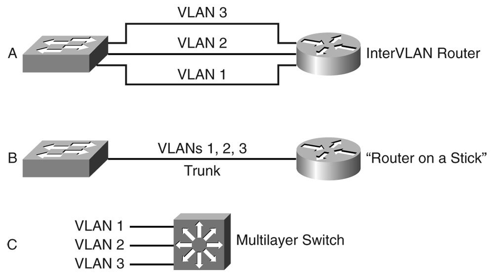
InterVLAN routing can be performed by an external router that connects to each of the VLANs on a switch. Separate physical connections can be used, or the router can access each of the VLANs through a single trunk link. Part A of Figure 12-1 illustrates this concept. The external router also can connect to the switch through a single trunk link, carrying all the necessary VLANs, as illustrated in Part B of Figure 12-1. Part B illustrates what commonly is referred to as a “router on a stick” or a “one-armed router” because the router needs only a single interface to do its job.
Finally, Part C of Figure 12-1 shows how the routing and switching functions can be combined into one device: a multilayer switch. No external router is needed.
Types of Interfaces
Multilayer switches can perform both Layer 2 switching and interVLAN routing, as appropriate. Layer 2 switching occurs between interfaces that are assigned to Layer 2 VLANs or Layer 2 trunks. Layer 3 switching can occur between any type of interface, as long as the interface can have a Layer 3 address assigned to it.
As with a router, a multilayer switch can assign a Layer 3 address to a physical interface. It also can assign a Layer 3 address to a logical interface that represents an entire VLAN. This is known as a switched virtual interface (SVI).
Configuring InterVLAN Routing
InterVLAN routing first requires that routing be enabled for the Layer 3 protocol. In addition, you must configure static routes or a dynamic routing protocol. These topics are covered fully in the BSCI course.
Because a multilayer switch supports many different types of interfaces for Layer 2 or Layer 3 switching, you must define each interface on a switch that will be used. By default, every switch port on platforms such as the Catalyst 2950, 3560, or 4500 is a Layer 2 interface, whereas every switch port on a Catalyst 6500 (native IOS) is a Layer 3 interface. If another type or mode is needed, you must explicitly configure it.
A port is either in Layer 2 or Layer 3 mode, depending on the use of the switchport configuration command. You can display a port’s current mode with the following command:
Switch# show interface type mod/num switchport
If the Switchport: line in the command output is shown as enabled, the port is in Layer 2 mode. If this line is shown as disabled, as in the following example, the port is in Layer 3 mode:
Switch# show interface gigabitethernet 0/1 switchport
Name: Gi0/1
Switchport: Disabled
Switch#
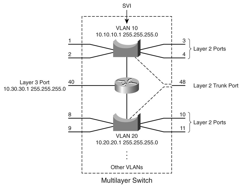
Figure 12-2 shows how the different types of interface modes can be used within a single switch.
Layer 2 Port Configuration
By default, all switch ports on Catalyst 2950, 3560, and 4500 platforms operate in Layer 2 mode. If you need to reconfigure a port for Layer 2 functionality, use the following command sequence:
Switch(config)# interface type mod/num
Switch(config-if)# switchport
Catalyst Switch with Various Types of Ports
The switchport command puts the port in Layer 2 mode. Then you can use other switchport command keywords to configure trunking, access VLANs, and so on. As displayed in Figure 12-2, several Layer 2 ports exist, each assigned to a specific VLAN. A Layer 2 port also can act as a trunk, transporting multiple VLANs.
Layer 3 Port Configuration
Physical switch ports also can operate as Layer 3 interfaces, where a Layer 3 network address is assigned and routing can occur, as shown previously in Figure 12-2. By default, all switch ports on the Catalyst 6500 platform (native IOS) operate in the Layer 3 mode. For Layer 3 functionality, you must explicitly configure switch ports with the following command sequence:
Switch(config)# interface type mod/num
Switch(config-if)# no switchport
Switch(config-if)# ip address ip-address mask [secondary]
The no switchport command takes the port out of Layer 2 operation. You then can assign a network address to the port, as you would to a router interface.
Keep in mind that a Layer 3 port assigns a network address to one specific physical interface. If several interfaces are bundled as an EtherChannel, the EtherChannel can become a Layer 3 port too. In that case, the network address is assigned to the port-channel interface—not to the individual physical links within the channel.
SVI Port Configuration
On a multilayer switch, you also can enable Layer 3 functionality for an entire VLAN on the switch. This allows a network address to be assigned to a logical interface: that of the VLAN itself. This is useful when the switch has many ports assigned to a common VLAN, and routing is needed in and out of that VLAN.
If you refer to Figure 12-2, you can see how an IP address is applied to the switched virtual interface called VLAN 10. Notice that the SVI itself has no physical connection to the outside world; to reach the outside, VLAN 10 must extend through a Layer 2 port or trunk.
The logical Layer 3 interface is known as an SVI. However, when it is configured, it uses the much more intuitive interface name vlan vlan-id, as if the VLAN itself is a physical interface. First, define or identify the VLAN interface; then assign any Layer 3 functionality to it with the following configuration commands:
Switch(config)# interface vlan vlan-id
Switch(config-if)# ip address ip-address mask [secondary]
The VLAN must be defined and active on the switch before the SVI can be used. Make sure that the new VLAN interface also is enabled with the no shutdown interface configuration command.
Note – The VLAN and the SVI are configured separately, even though they interoperate. Creating or configuring the SVI doesn’t create or configure the VLAN; you still must define each one independently.
As an example, the following commands show how VLAN 100 is created and then defined as a Layer 3 SVI:
Multilayer Switching with CEF
Catalyst switches can use several methods to forward packets based on Layer 3 and Layer 4 information. The current generation of Catalyst multilayer switches uses the efficient Cisco Express Forwarding (CEF) method. This section describes the evolution of multilayer switching and discusses CEF in detail. Although CEF is easy to configure and use, the underlying switching mechanisms are more involved and should be understood.
Traditional MLS Overview
Multilayer switching began as a dual effort between a route processor (RP) and a switching engine (SE). The basic idea is to “route once and switch many.” The RP receives the first packet of a new traffic flow between two hosts, as usual. A routing decision is made, and the packet is forwarded toward the destination.
To participate in multilayer switching, the SE must know the identity of each RP. The SE then can listen in to the first packet going to the router and also going away from the router. If the SE can switch the packet in both directions, it can learn a “shortcut path” so that subsequent packets of the same flow can be switched directly to the destination port without passing through the RP.
This technique also is known as NetFlow switching or route cache switching. Traditionally, NetFlow switching was performed on Cisco hardware, such as the Catalyst 6000 Supervisor 1/1a and Multilayer Switch Feature Card (MSFC), Catalyst 5500 with a Route Switch Module (RSM), Route Switch Feature Card (RSFC), or external router. Basically, the hardware consisted of an independent RP component and a NetFlow-capable SE component.
CEF Overview
NetFlow switching has given way to a more efficient form of multilayer switching: Cisco Express Forwarding. Cisco developed CEF for its line of routers, offering high-performance packet forwarding through the use of dynamic lookup tables.
CEF also has been carried over to the Catalyst switching platforms. The following platforms all perform CEF in hardware:
Catalyst 6500 Supervisor 720 (with an integrated MSFC3)
Catalyst 6500 Supervisor 2/MSFC2 combination
Catalyst 4500 Supervisor III, IV, and V
Fixed-configuration switches, such as the Catalyst 3750, 3560, 3550, and 2950
CEF runs by default, taking advantage of the specialized hardware.
A CEF-based multilayer switch consists of two basic functional blocks, as shown in Figure 12-3: The Layer 3 Engine is involved in building routing information that the Layer 3 Forwarding Engine can use to switch packets in hardware.
Packet Flow Through a CEF-Based Multilayer Switch
Forwarding Information Base
The Layer 3 engine (essentially a router) maintains routing information, whether from static routes or dynamic routing protocols. Basically, the routing table is reformatted into an ordered list with the most specific route first, for each IP destination subnet in the table. The new format is called a Forwarding Information Base (FIB) and contains routing or forwarding information that the network prefix can reference.
In other words, a route to 10.1.0.0/16 might be contained in the FIB along with routes to 10.1.1.0/24 and 10.1.1.128/25, if those exist. Notice that these examples are increasingly more specific subnets, as designated by the longer subnet masks. In the FIB, these would be ordered with the most specific, or longest match, first, followed by less specific subnets. When the switch receives a packet, it easily can examine the destination address and find the longest-match destination route entry in the FIB.
The FIB also contains the next-hop address for each entry. When a longest-match entry is found in the FIB, the Layer 3 next-hop address is found, too.
You might be surprised to know that the FIB also contains host route (subnet mask 255.255.255.255) entries. These normally are not found in the routing table unless they are advertised or manually configured. Host routes are maintained in the FIB for the most efficient routing lookup to directly connected or adjacent hosts.
As with a routing table, the FIB is dynamic in nature. When the Layer 3 engine sees a change in the routing topology, it sends an update to the FIB. Anytime the routing table receives a change to a route prefix or the next-hop address, the FIB receives the same change. Also, if a next-hop address is changed or aged out of the Address Resolution Protocol (ARP) table, the FIB must reflect the same change.
You can display FIB table entries related to a specific interface or VLAN with the following form of the show ip cef command:
Switch# show ip cef [type mod/num | vlan vlan-id] [detail]
The FIB entries corresponding to the VLAN 101 switched virtual interface might be shown as demonstrated in Example 12-1.
Example 12-1 Displaying FIB Table Entries for a Specified VLAN
Switch# show ip cef vlan 101
Prefix       Next Hop       Interface
10.1.1.0/24     attached       Vlan101
10.1.1.2/32     10.1.1.2       Vlan101
10.1.1.3/32     10.1.1.3       Vlan101
Switch#
You also can view FIB entries by specifying an IP prefix address and mask, using the following form of the show ip cef command:
Switch# show ip cef [prefix-ip prefix-mask] [longer-prefixes] [detail]
The output in Example 12-2 displays any subnet within 10.1.0.0/16 that is known by the switch, regardless of the prefix or mask length. Normally, only an exact match of the IP prefix and mask will be displayed if it exists in the CEF table. To see other longer match entries, you can add the longer-prefixes keyword.
Example 12-2 Displaying FIB Table Entries for a Specified IP Prefix Address/Mask
Switch# show ip cef 10.1.0.0 255.255.0.0 longer-prefixes
Prefix       Next Hop       Interface
10.1.1.0/24     attached       Vlan101
10.1.1.2/32     10.1.1.2       Vlan101
10.1.1.3/32     10.1.1.3       Vlan101
10.1.2.0/24     attached       Vlan102
10.1.3.0/26     192.168.1.2     Vlan99
          192.168.1.3     Vlan99
10.1.3.64/26    192.168.1.2     Vlan99
          192.168.1.3     Vlan99
10.1.3.128/26    192.168.1.4     Vlan99
          192.168.1.3     Vlan99
[output omitted]
Switch#
Notice that the first three entries are the same ones listed in Example 12-1. Other subnets also are displayed, along with their next-hop router addresses and switch interfaces.
You can add the detail keyword to see more information about each FIB table entry for CEF, as demonstrated in Example 12-3.
Example 12-3 Displaying Detailed CEF Entry Information
Switch# show ip cef 10.1.3.0 255.255.255.192 detail
10.1.3.0/26, version 270, epoch 0, per-destination sharing
0 packets, 0 bytes
 via 192.168.1.2, Vlan99, 0 dependencies
  traffic share 1
  next hop 192.168.1.2, Vlan99
  valid adjacency
 via 192.168.1.3, Vlan99, 0 dependencies
  traffic share 1
  next hop 192.168.1.3, Vlan99
  valid adjacency
 0 packets, 0 bytes switched through the prefix
 tmstats: external 0 packets, 0 bytes
      internal 0 packets, 0 bytes
Switch#
The version number describes the number of times the CEF entry has been updated since the table was generated. The epoch number denotes the number of times the CEF table has been flushed and regenerated as a whole. The 10.1.3.0/26 subnet has two next-hop router addresses, so the local switch is using per-destination load sharing between the two routers.
After the FIB is built, packets can be forwarded along the bottom dashed path in Figure 12-3. This follows the hardware switching process, in which no “expensive” or time-consuming operations are needed. At times, however, a packet cannot be switched in hardware, according to the FIB. Packets then are marked as “CEF punt” and immediately are sent to the Layer 3 engine for further processing, as shown in the top dashed path in Figure 12-3. Some of the conditions that can cause this are as follows:
An entry cannot be located in the FIB
The FIB table is full
The IP Time To Live (TTL) has expired
The maximum transmission unit (MTU) is exceeded, and the packet must be fragmented
An Internet Control Message Protocol (ICMP) redirect is involved
The encapsulation type is not supported
Packets are tunneled, requiring a compression or encryption operation
An access list with the log option is triggered
A Network Address Translation (NAT) operation must be performed (except on the Catalyst 6500 Supervisor 720, which can handle NAT in hardware)
CEF operations can be handled on a single hardware platform, such as the Catalyst 3560 and 3750 switches. The FIB is generated and contained centrally in the switch. CEF also can be optimized through the use of specialized forwarding hardware, using the following techniques:
Accelerated CEF (aCEF)—CEF is distributed across multiple Layer 3 forwarding engines, typically located on Catalyst 6500 line cards. These engines do not have the capability to store and use the entire FIB, so only a portion of the FIB is downloaded to them at any time. This functions as an FIB “cache,” containing entries that are likely to be used again. If FIB entries are not found in the cache, requests are sent to the Layer 3 engine for more FIB information. The net result is that CEF is accelerated on the line cards, but not necessarily at a sustained wire-speed rate.
Distributed CEF (dCEF)—CEF can be distributed completely among multiple Layer 3 forwarding engines for even greater performance. Because the FIB is self-contained for complete Layer 3 forwarding, it can be replicated across any number of independent Layer 3 forwarding engines. The Catalyst 6500 has line cards that support dCEF, each with its own FIB table and forwarding engine. A central Layer 3 engine (the MSFC3, for example) maintains the routing table and generates the FIB, which is then dynamically downloaded in full to each of the line cards.
Adjacency Table
A router normally maintains a routing table containing Layer 3 network and next-hop information, and an ARP table containing Layer 3 to Layer 2 address mapping. These tables are kept independently.
Recall that the FIB keeps the Layer 3 next-hop address for each entry. To streamline packet forwarding even more, the FIB has corresponding Layer 2 information for every next-hop entry. This portion of the FIB is called the adjacency table, consisting of the MAC addresses of nodes that can be reached in a single Layer 2 hop.
You can display the adjacency table’s contents with the following command:
Switch# show adjacency [type mod/num | vlan vlan-id] [summary | detail]
As an example, the total number of adjacencies known on each physical or VLAN interface can be displayed with the show adjacency summary command, as demonstrated in Example 12-4.
Example 12-4 Displaying the Total Number of Known Adjacencies
Switch# show adjacency summary
Adjacency Table has 106 adjacencies
 Table epoch: 0 (106 entries at this epoch)
 Interface         Adjacency Count
 Vlan99          21
 Vlan101          3
 Vlan102          1
 Vlan103          47
 Vlan104          7
 Vlan105          27
Switch#
Adjacencies are kept for each next-hop router and each host that is connected directly to the local switch. You can see more detailed information about the adjacencies by using the detail keyword, as demonstrated in Example 12-5.
Example 12-5 Displaying Detailed Information About Adjacencies
Switch# show adjacency vlan 99 detail
Protocol Interface         Address
IP    Vlan99          192.168.1.2(5)
                  0 packets, 0 bytes
                  000A5E45B145000E387D51000800
                  ARP    01:52:50
                  Epoch: 0
IP    Vlan99          192.168.1.3(5)
                  1 packets, 104 bytes
                  000CF1C909A0000E387D51000800
                  ARP    04:02:11
                  Epoch: 0
Notice that the adjacency entries include both the IP address (Layer 3) and the MAC address (Layer 2) of the directly attached host. The MAC address could be shown as the first six octets of the long string of hex digits (as shaded in the previous output) or on a line by itself. The remainder of the string of hex digits contains the MAC address of the Layer 3 engine’s interface (six octets, corresponding to the Vlan99 interface in the example) and the EtherType value (two octets, where 0800 denotes IP).
The adjacency table information is built from the ARP table. Example 12-5 shows adjacency with the age of its ARP entry. As a next-hop address receives a valid ARP entry, the adjacency table is updated. If an ARP entry does not exist, the FIB entry is marked as “CEF glean.” This means that the Layer 3 forwarding engine can’t forward the packet in hardware because of the missing Layer 2 next-hop address. The packet is sent to the Layer 3 engine so that it can generate an ARP request and receive an ARP reply. This is known as the CEF glean state, in which the Layer 3 engine must glean the next-hop destination’s MAC address.
The glean state can be demonstrated in several ways, as demonstrated in Example 12-6.
Example 12-6 Displaying Adjacencies in the CEF Glean State
Switch# show ip cef adjacency glean
Prefix       Next Hop       Interface
10.1.1.2/32     attached       Vlan101
127.0.0.0/8     attached       EOBC0/0
[output omitted]
Switch# show ip arp 10.1.1.2 Switch# show ip cef 10.1.1.2 255.255.255.255 detail 10.1.1.2/32, version 688, epoch 0, attached, connected 0 packets, 0 bytes via Vlan101, 0 dependencies valid glean adjacency Switch#
Notice that the FIB entry for directly connected host 10.1.1.2/32 is present but listed in the glean state. The show ip arp command shows that there is no valid ARP entry for the IP address.
During the time that an FIB entry is in the CEF glean state waiting for the ARP resolution, subsequent packets to that host are immediately dropped so that the input queues do not fill and the Layer 3 engine does not become too busy worrying about the need for duplicate ARP requests. This is called ARP throttling or throttling adjacency. If an ARP reply is not received in 2 seconds, the throttling is released so that another ARP request can be triggered. Otherwise, after an ARP reply is received, the throttling is released, the FIB entry can be completed, and packets can be forwarded completely in hardware.
The adjacency table also can contain other types of entries so that packets can be handled efficiently. For example, you might see the following adjacency types listed:
Null adjacency—Used to switch packets destined for the null interface. The null interface always is defined on a router or switch; it represents a logical interface that silently absorbs packets without actually forwarding them.
Drop adjacency—Used to switch packets that can’t be forwarded normally. In effect, these packets are dropped without being forwarded. Packets can be dropped because of an encapsulation failure, an unresolved address, an unsupported protocol, no valid route present, no valid adjacency, or a checksum error. You can gauge drop adjacency activity with the following command:
Switch# show cef drop
CEF Drop Statistics
Slot Encap_fail Unresolved Unsupported  No_route   No_adj ChkSum_Err
RP    8799327      1    45827   5089667     32      0
Switch#
Discard adjacency—Used when packets must be discarded because of an access list or other policy action.
Punt adjacency—Used when packets must be sent to the Layer 3 engine for further processing. You can gauge the CEF punt activity by looking at the various punt adjacency reasons listed by the show cef not-cef-switched command:
Switch# show cef not-cef-switched
CEF Packets passed on to next switching layer
Slot No_adj No_encap Unsupp'ted Redirect Receive Options  Access   Frag
RP  3579706    0      0    0 41258564    0    0    0
Switch#
The reasons shown are as follows:
No_adj—An incomplete adjacency
No_encap—An incomplete ARP resolution
Unsupp’ted—Unsupported packet features
Redirect—ICMP redirect
Receive—Layer 3 engine interfaces; includes packets destined for IP addresses that are assigned to interfaces on the Layer 3 engine, IP network addresses, and IP broadcast addresses
Options—IP options present
Access—Access list evaluation failure
Frag—Fragmentation failure
Packet Rewrite
When a multilayer switch finds valid entries in the FIB and adjacency tables, a packet is almost ready to be forwarded. One step remains: The packet header information must be rewritten. Keep in mind that multilayer switching occurs as quick table lookups to find the next-hop address and the outbound switch port. The packet is untouched and still has the original destination MAC address of the switch itself. The IP header also must be adjusted, as if a traditional router had done the forwarding.
The switch has an additional functional block that performs a packet rewrite in real time. The packet rewrite engine (shown in Figure 12-3) makes the following changes to the packet just before forwarding:
Layer 2 destination address—Changed to the next-hop device’s MAC address
Layer 2 source address—Changed to the outbound Layer 3 switch interface’s MAC address
Layer 3 IP Time To Live (TTL)—Decremented by one because one router hop has just occurred
Layer 3 IP checksum—Recalculated to include changes to the IP header
Layer 2 frame checksum—Recalculated to include changes to the Layer 2 and Layer 3 headers
A traditional router normally would make the same changes to each packet. The multilayer switch must act as if a traditional router were being used, making identical changes. However, the multilayer switch can do this very efficiently with dedicated packet-rewrite hardware and address information obtained from table lookups.
Configuring CEF
CEF is enabled on all CEF-capable Catalyst switches by default. In fact, the Catalyst 6500 (with a Supervisor 720 and its integrated MSFC3, or a Supervisor 2 and MSFC2 combination) runs CEF inherently, so CEF never can be disabled.
Tip – Switches such as the Catalyst 3750 and 4500 run CEF by default, but you can disable CEF on a per-interface basis. You can use the no ip route-cache cef and no ip cef interface configuration commands to disable CEF on the Catalyst 3750 and 4500, respectively.
You should always keep CEF enabled whenever possible, except when you need to disable it for debugging purposes.
Fallback Bridging
For protocols that CEF can’t route or switch, a technique known as fallback bridging is used. Sample protocols are IPX and AppleTalk, which are routable but not supported by CEF, as well as SNA and LAT, which are not routable. To summarize fallback bridging operation, each SVI associated with a VLAN in which nonroutable protocols are being used is assigned to a bridge group. Packets that cannot be routed from one VLAN to another are bridged transparently instead, as long as the two VLANs belong to the same bridge group.
Only the Catalyst 3560 and 3750 offer fallback bridging; these platforms can CEF-switch IP packets, but no others. The Catalyst 4500 and 6500 (all Supervisor models running Cisco IOS Software) also can CEF-switch IP but can handle other routable protocols more slowly with their Layer 3 engines. Those two platforms have no need for fallback bridging.
Bridge groups used in fallback bridging do not interact with normal Layer 2 switching (also using bridging). They do use a special Spanning Tree Protocol to maintain loop-free fallback bridging, but these bridge protocol data units (BPDU) are not exchanged with other 802.1D, Rapid Spanning Tree Protocol (RSTP), or Multiple Spanning Tree (MST) BPDUs on VLANs. Instead, the VLAN-bridge STP is used, with one instance per fallback bridge group.
To configure fallback bridging, first decide which VLANs have traffic that CEF cannot route. Begin by enabling a fallback bridge group and its instance of the VLAN-bridge STP:
Switch(config)# bridge-group bridge-group protocol vlan-bridge
Next, for each VLAN SVI in which nonroutable traffic will be bridged, assign it to the appropriate bridge group:
Switch(config)# interface vlan vlan-id
Switch(config-if)# bridge-group bridge-group
You can configure up to 31 different fallback bridge groups on a switch. Although the VLAN bridge STP instance running on each bridge group does not interact with normal 802.1D STP, it does behave similarly. For example, you can configure the bridge priority, port priority and cost, Hello timer, Forward Delay timer, and Max Age timer. These parameters all should look familiar because they are used in the 802.1D STP. Rather than using the spanning-tree command to adjust the parameter values, you must adjust them according to the bridge group number with the bridge-group bridge-group command keywords.
Verifying Multilayer Switching
The multilayer switching topics presented in this chapter are not difficult to configure; however, you might need to verify how a switch is forwarding packets. In particular, the following sections discuss the commands that you can use to verify the operation of InterVLAN routing, CEF, and fallback bridging.
Verifying InterVLAN Routing
To verify the configuration of a Layer 2 port, you can use the following EXEC command:
Switch# show interface type mod/num switchport
The output from this command displays the access VLAN or the trunking mode and native VLAN. The administrative modes reflect what has been configured for the port, whereas the operational modes show the port’s active status.
You can use this same command to verify the configuration of a Layer 3 or routed port. In this case, you should see the switchport (Layer 2) mode disabled, as in Example 12-7.
Example 12-7 Verifying Configuration of a Layer 3 Switch Port
Switch# show interface fastethernet 0/16 switchport
Name: Fa0/16
Switchport: Disabled
Switch#
To see the physical interface’s status and counters, use the command without the switchport keyword. To see a summary listing of all interfaces, you can use the show interface status command.
To verify the configuration of an SVI, you can use the following EXEC command:
Switch# show interface vlan vlan-id
The VLAN interface should be up, with the line protocol also up. If this is not true, either the interface is disabled with the shutdown command or the VLAN itself has not been defined on the switch. Use the show vlan command to see a list of configured VLANs.
Example 12-8 shows the output produced from the show vlan command. Notice that each defined VLAN is shown, along with the switch ports that are assigned to it.
Example 12-8 Displaying a List of Configured VLANs
Switch# show vlan

VLAN Name               Status  Ports
---- -------------------------------- --------- -------------------------------
1  default             active  Fa0/5, Fa0/6, Fa0/7, Fa0/8
                        Fa0/9, Fa0/10, Fa0/11, Fa0/12
                        Fa0/13, Fa0/14, Fa0/15, Fa0/17
                        Fa0/18, Fa0/19, Fa0/20, Fa0/21
                        Fa0/22, Fa0/23, Fa0/24, Fa0/25
                        Fa0/26, Fa0/27, Fa0/28, Fa0/29
                        Fa0/30, Fa0/32, Fa0/33, Fa0/34
                        Fa0/36, Fa0/37, Fa0/38, Fa0/39
                        Fa0/41, Fa0/42, Fa0/43, Fa0/44
                        Fa0/45, Fa0/46, Fa0/47, Gi0/1
                        Gi0/2
2  VLAN0002             active  Fa0/40
5  VLAN0005             active
10  VLAN0010             active
11  VLAN0011             active  Fa0/31
12  VLAN0012             active
99  VLAN0099             active  Fa0/35
Switch#
You also can display the IP-related information about a switch interface with the show ip interface command, as demonstrated in Example 12-9.
Example 12-9 Displaying IP-Related Information About a Switch Interface
Switch# show ip interface vlan 101
Vlan101 is up, line protocol is up
 Internet address is 10.1.1.1/24
 Broadcast address is 255.255.255.255
 Address determined by setup command
 MTU is 1500 bytes
 Helper address is not set
 Directed broadcast forwarding is disabled
 Outgoing access list is not set
 Inbound access list is not set
 Proxy ARP is enabled
 Local Proxy ARP is disabled
 Security level is default
 Split horizon is enabled
 ICMP redirects are always sent
 ICMP unreachables are always sent
 ICMP mask replies are never sent
 IP fast switching is enabled
 IP fast switching on the same interface is disabled
 IP Flow switching is disabled
 IP CEF switching is enabled
 IP Feature Fast switching turbo vector
 IP Feature CEF switching turbo vector
 IP multicast fast switching is enabled
 IP multicast distributed fast switching is disabled
 IP route-cache flags are Fast, Distributed, CEF
 Router Discovery is disabled
 IP output packet accounting is disabled
 IP access violation accounting is disabled
 TCP/IP header compression is disabled
 RTP/IP header compression is disabled
 Probe proxy name replies are disabled
 Policy routing is disabled
 Network address translation is disabled
 WCCP Redirect outbound is disabled
 WCCP Redirect inbound is disabled
 WCCP Redirect exclude is disabled
 BGP Policy Mapping is disabled
 Sampled Netflow is disabled
 IP multicast multilayer switching is disabled
Switch#
You can use the show ip interface brief command to see a summary listing of the interfaces involved in routing IP traffic, as demonstrated in Example 12-10.
Example 12-10 Displaying a Summary Listing of Interfaces Routing IP Traffic
Switch# show ip interface brief
Interface         IP-Address   OK? Method Status        Protocol
Vlan1           unassigned   YES NVRAM administratively down down
Vlan54           10.3.1.6    YES manual up          up
Vlan101          10.1.1.1    YES manual up          up
GigabitEthernet1/1     10.1.5.1    YES manual up          up
[output omitted]
Switch#
Verifying CEF
CEF operation depends on the correct routing information being generated and downloaded to the Layer 3 forwarding engine hardware. This information is contained in the FIB and is maintained dynamically. To view the entire FIB, use the following EXEC command:
Switch# show ip cef
Example 12-11 shows sample output from this command.
Example 12-11 Displaying the FIB Contents for a Switch
Switch# show ip cef
Prefix       Next Hop       Interface
0.0.0.0/32     receive
192.168.199.0/24  attached       Vlan1
192.168.199.0/32  receive
192.168.199.1/32  receive
192.168.199.2/32  192.168.199.2    Vlan1
192.168.199.255/32 receive
Switch#
On this switch, only VLAN 1 has been configured with the IP address 192.168.199.1 255.255.255.0. Notice several things about the FIB for such a small configuration:
0.0.0.0/32—An FIB entry has been reserved for the default route. No next hop is defined, so the entry is marked “receive” so that packets will be sent to the Layer 3 engine for further processing.
192.168.199.0/24—The subnet assigned to the VLAN 1 interface is given its own entry. This is marked “attached” because it is connected directly to an SVI, VLAN 1.
192.168.199.0/32—An FIB entry has been reserved for the exact network address. This is used to contain an adjacency for packets sent to the network address, if the network is not directly connected. In this case, there is no adjacency, and the entry is marked “receive.”
192.168.199.1/32—An entry has been reserved for the VLAN 1 SVI’s IP address. Notice that this is a host route (/32). Packets destined for the VLAN 1 interface must be dealt with internally, so the entry is marked “receive.”
192.168.199.2/32—This is an entry for a neighboring multilayer switch, found on the VLAN 1 interface. The next-hop field has been filled in with the same IP address, denoting that an adjacency is available.
192.168.199.255/32—An FIB entry has been reserved for the 192.168.199.0 subnet’s broadcast address. The route processor (Layer 3 engine) handles all directed broadcasts, so the entry is marked “receive.”
To see complete FIB table information for a specific interface, use the following EXEC command:
Switch# show ip cef type mod/num [detail]
Verifying Fallback Bridging
To verify the operation of fallback bridging, you can use the following EXEC commands:
Switch# show bridge group
Switch# show bridge bridge-group [verbose]
The first command shows a summary of all active fallback bridge groups, along with their STP states. The second command displays the bridging table contents for a specific fallback bridge group.
Foundation Summary
The Foundation Summary is a collection of information that provides a convenient review of many key concepts in this chapter. If you are already comfortable with the topics in this chapter, this summary can help you recall a few details. If you just read this chapter, this review should help solidify some key facts. If you are doing your final preparation before the exam, this information is a convenient way to review the day before the exam.
Table 12-2 InterVLAN Routing Configuration Commands
Task | Command Syntax |
Put a port into Layer 2 mode | Switch(config-if)# switchport |
Put a port into Layer 3 mode | Switch(config-if)# no switchport |
Define an SVI | Switch(config)# interface vlan vlan-id |
Components of CEF:
Forwarding Information Base (FIB)—Contains routing and next-hop information. Lookups are performed according to longest-match IP prefix.
Adjacency table—Contains Layer 2 address information for next-hop FIB entries that are one hop away.
Packet rewrite—Hardware dedicated to rewriting the Layer 2 and Layer 3 header information of outbound packets after the forwarding decisions have been made.
Table 12-3 Fallback Bridging Configuration Commands
Task | Command Syntax |
Define a fallback bridge group | Switch(config)# bridge-group bridge-group protocol vlan-bridge |
Assign an interface to a bridge group | Switch(config)# interface vlan vlan-id Switch(config-if)# bridge-group bridge-group |
Table 12-4 Multilayer Switching Verification Commands
Task | Command Syntax |
Show a Layer 2 port status | Switch# show interface type mod/num switchport |
Show a Layer 3 port status | Switch# show interface type mod/num |
Show an SVI status | Switch# show interface vlan vlan-id |
View the FIB contents | Switch# show ip cef |
View FIB information for an interface | Switch# show ip cef [type mod/num | vlan vlan-id] [detail] |
View FIB information for an IP prefix | Switch# show ip cef [prefix-ip prefix-mask] [longer-prefixes] [detail] |
View FIB adjacency information | Switch# show adjacency [type mod/num | vlan vlan-id] [summary | detail] |
View counters for packets not switched by CEF | Switch# show cef not-cef-switched |
Show fallback bridge group status | Switch# show bridge group |
Show fallback bridging table contents | Switch# show bridge bridge-group |
Q&A
The questions and scenarios in this book are more difficult than what you should experience on the actual exam. The questions do not attempt to cover more breadth or depth than the exam; however, they are designed to make sure that you know the answers. Rather than allowing you to derive the answers from clues hidden inside the questions themselves, the questions challenge your understanding and recall of the subject. Hopefully, these questions will help limit the number of exam questions on which you narrow your choices to two options and then guess.
You can find the answers to these questions in Appendix A.
What might you need to implement interVLAN routing?
Can interVLAN routing be performed over a single trunk link?
To configure an SVI, what commands are needed?
What command can verify the VLAN assignments on a Layer 2 port?
A switch has the following interface configurations in its running configuration:
interface fastethernet 0/1
 switchport access vlan 5
!
interface vlan 5
 ip address 192.168.10.1 255.255.255.0
 no shutdown
What is necessary for packets to get from the FastEthernet interface to the VLAN 5 SVI?
What is the source of FIB information?
How often is the FIB updated?
What is meant by the term CEF punt?
What happens to the FIB when distributed CEF (dCEF) is used?
What happens during a CEF glean process?
What does a multilayer switch do to the IP TTL value just before a packet is forwarded?
What is fallback bridging?
Is it possible for an SVI to go down? If so, for what reasons?
Copyright © 2007 Pearson Education. All rights reserved.