Cisco Press

An Internet service provider’s simple MPLS VPN design
Understanding the CEF and MPLS relationship
CEF considerations when troubleshooting MPLS VPN across various platforms
CEF and MPLS VPN load-sharing considerations
Understanding CEF operation in a Multiprotocol Label Switching (MPLS) environment is important for design stability and troubleshooting. This chapter analyzes CEF in MPLS Virtual Private Network (VPN) applications across Cisco platforms. Service providers and enterprises are increasingly using MPLS to provide connection-oriented services using an IP infrastructure. They also deploy MPLS VPNs for reasons including scalability, security, and flexibility. Because of increased MPLS VPN usage, you need to understand CEF’s role, especially when troubleshooting.
CEF is the fundamental switching path for MPLS. Without CEF, MPLS forwarding does not occur. MPLS forwarding relies heavily on the IP routing table and the CEF architecture. Therefore, MPLS VPN relies on CEF because MPLS VPN depends on MPLS for successful operation.
This chapter assumes a basic understanding of MPLS VPNs. Although issues can occur with MPLS VPN setup, label distribution protocol (LDP), and operation, many times the issues relate to label mismatches stored in CEF or some other CEF inconsistency. Sometimes administrators believe the issue is with CEF, but it is with routing design. This chapter discusses some of these issues across various Cisco platforms.
An Internet Service Provider’s Simple MPLS VPN Design
An ISP network typically consists of edge routers (often called provider edge, or PE, routers) that connect to customer edge (CE) routers and other service provider devices. In Figure 7-1, the ISP’s PE routers receive customer routes (VPNv4 routes) through external BGP (eBGP) or some other routing protocol and send them through internal BGP (iBGP) to all other PE routers. Most networks use route reflectors to avoid the full mesh of iBGP connections, so all iBGP speakers have a session to the route reflectors. This is the basic structure of an ISP network for MPLS VPN implementation. Table 7-1 defines the type of devices in an MPLS VPN network and their awareness of MPLS VPN.

Typical ISP MPLS VPN Implementation
Table 7-1 MPLS VPN Device Type and Awareness
| Type of Device | Description | MPLS VPN Awareness |
|---|---|---|
| Provider (P) router | Part of provider network that interfaces with PE and other P routers | No |
| Provider edge (PE) router | Part of the provider network that interfaces with the CE router and P and PE routers | Yes |
| Customer edge (CE) router | Part of the customer network that interfaces with the PE | No |
MPLS VPN uses a shared infrastructure but provides security for customers’ traffic. If site Routers CE1 and CE3 belong to the same customer and VPN, their traffic is segmented from other customers’ traffic and marked with a label. The PE routers maintain a separate routing table for each customer VPN called a virtual routing and forwarding (VRF) table.
While the VRF tables provide the isolation between customers, the data from these routing tables is exchanged between PE routers to enable data transfer between sites attached to different PE routers. The core routers in the provider network (P routers) that provide transport across the provider’s backbone are not aware of customer routes.
The transit across the backbone is performed by using the labels that had been exchanged for routes in the global IP routing table. So, in the most common form, two labels are added to customer traffic. The core routers do not care about the customers’ IP packet for forwarding, but see a labeled packet targeted toward an egress PE router. The egress PE router performs label switching on the second label (VPN label that was previously assigned), and either forwards the IP packet toward the CE router or performs another IP lookup in the VRF. The end-to-end path between CE1 and CE3 is an MPLS Label Switch Path (LSP) tunnel. Figure 7-2 illustrates a typical LSP between two sites.
Typical LSP Between Two Sites
Understanding the CEF and MPLS VPN Relationship
An MPLS VPN depends on CEF functionality. MPLS creates its own database for lookups called the Label Forwarding Information Base (LFIB), but it uses the CEF FIB as a source of this information. If CEF cannot resolve a route, the label cannot switch to a destination either. The label process path of an MPLS VPN packet between customer sites is label imposition, label swapping, and then label disposition.
Label imposition occurs when the PE router forwards based on the IP header and adds an MPLS label to the packet upon entering an MPLS network. In the direction of label imposition, the router switches packets based on a CEF table lookup to find the next hop and adds the appropriate label information stored in the FIB for the destination.
When a router performs label swapping in the core on an MPLS packet, the router does an MPLS table lookup. The router derives this MPLS table (LFIB) from information in the CEF table and the Label Information Base (LIB). Path changes that occur to reach a destination can result in changes in the FIB and LFIB. Multiple paths known through different routers can result in one label for each path. The router derives label load-sharing information from the CEF load-sharing information. For load sharing, the router looks inside the packet to determine whether it is an IP version 4 (IPv4) packet. If it is an IPv4 packet, CEF uses the IP addresses for hashing. For example, in a P-P scenario, the P router looks below the MPLS labels and inside the IP header to use the IP addresses to allocate the correct hash bucket for load sharing but not to make a forwarding decision. The P router makes the forwarding decision based on the topmost label.
Label disposition occurs when the PE router receives an MPLS packet, makes a forwarding decision based on the MPLS label, removes the label, and sends an IP packet. The PE router uses the LFIB for path determination for a packet in this direction.
Table 7-2 summarizes which structures to look at when troubleshooting. As stated previously, a special iBGP session facilitates the advertisement of VPNv4 prefixes and their labels between PE routers. At the advertising PE, BGP allocates labels for the VPN prefixes learned locally and installs them in the LFIB, which is the MPLS forwarding table. From a PE device perspective, locally learned prefixes are prefixes learned from the connected customer edge device by the PE. At the receiving PE, if BGP accepts the remotely learned VPN prefixes with labels based on the route-target importation, BGP installs the VPN prefixes in the VRF FIB, which is the CEF table. From the PE perspective, remotely learned prefixes are prefixes learned from another PE through eBGP. An IP lookup occurs only once at the ingress PE. In short, if the router receives an MPLS packet, lookup occurs in the LFIB. If the router receives an IP packet, lookup occurs in the FIB.
Table 7-2 Switching Structure Used by Function
| Structure | Command | Where to Use | Device Function |
|---|---|---|---|
| LFIB | show mpls forwarding | P routers | Label-to-label switching |
| LFIB | show mpls forwarding vrf | Advertising PE/egress PE routers for locally learned prefixes | Label-to-IP switching (disposition) |
| VRF FIB | show ip cef vrf | Receiving PE/ingress PE for remotely learned prefixes | IP-to-label switching (imposition) |
| FIB | show ip cef | CE | Normal routing/CEF switching |
It is best to relate to an example to show how CEF is important in each stage of the label process path. The following cases show how to verify proper operation of an MPLS VPN network and how to analyze the LFIB and VRF CEF tables across an LSP.
Case 1: Label Disposition
In Figure 7-3, an MPLS VPN tunnel (LSP) exists between PE1 and PE2. CE1 is advertising its LAN prefix 10.1.0.0/16 through eBGP to PE1. PE1 in turns advertises this local prefix through iBGP to other PE routers. PE1 must perform label disposition on traffic coming from the MPLS cloud toward 10.1.0.0/16. Therefore, to verify that PE1 has the information on how to reach 10.1.1.1 properly, you need to look at the LFIB on PE1. First, examine what label BGP assigns for this VPN prefix 10.1.0.0/16.
Example 7-1 Verifying BGP Label Assignment on Egress PE for 10.1.0.0/16
PE1#show ip bgp vpn vrf red label | include 10.1.0.0
  10.1.0.0/16   10.3.1.2    20/nolabel
PE1#show ip bgp vpn vrf red 10.1.1.1
BGP routing table entry for 1:1:10.1.0.0/16, version 25550
Paths: (1 available, best #1, table red)
 Advertised to non peer-group peers:
 192.168.4.4
 65001
  10.3.1.2 from 10.3.1.2 (10.3.1.6)
   Origin IGP, metric 0, localpref 100, valid, external, best
   Extended Community: RT:1:1,
   mpls labels in/out 20/nolabel
Now, check the LFIB to make sure that PE1 sees the local, expected label to receive as 20. In Example 7-2, notice that the LFIB sees the correct local label/tag as 20.
Example 7-2 Verifying the LFIB on Egress PE for 10.1.0.0/16
PE1#show mpls forwarding vrf red 10.1.1.1
Local Outgoing  Prefix      Bytes tag Outgoing  Next Hop
tag  tag or VC  or Tunnel Id   switched  interface
20   Untagged  10.1.0.0/16[V]  0     Se2/0   point2point
Note – The PE router typically installs a locally learned route from a CE in the VRF routing table, VRF CEF table, and LFIB. However, the PE usually only checks the LFIB when passing traffic to a CE because traffic destined for the CE is typically an incoming MPLS packet. A PE router can also receive an IP packet destined for a CE if two CE routers are in the same VRF, connected to the same PE router, and sending traffic to each other. So, if an incoming packet to a PE is an IP packet from a VPN site, look in the VRF CEF table. If an incoming packet is an MPLS packet, look in the LFIB.
Case 2: Label Imposition
For CE2 to reach CE1, PE2 must perform label imposition on an IP packet received from CE2. At the other end of the VPN tunnel, PE2 should also see the correct VPN label of 20 to reach 10.1.1.1. Look at the BGP table and the VRF FIB to confirm this, as shown in Example 7-3.
Example 7-3 Verifying BGP and VRF FIB on Ingress PE for 10.1.0.0/16
PE2#show ip bgp vpn vrf red 10.1.1.1
BGP routing table entry for 1:1:10.1.0.0/16, version 8
Paths: (1 available, best #1, table red)
 Advertised to non peer-group peers:
 10.4.1.2
 65001
  192.168.2.2 (metric 21) from 192.168.2.2 (192.168.2.2)
   Origin IGP, metric 0, localpref 100, valid, internal, best
   Extended Community: RT:1:1,
   mpls labels in/out nolabel/20
PE2#show ip cef vrf red 10.1.1.1
10.1.0.0/16, version 7, epoch 0, cached adjacency 172.16.3.1
0 packets, 0 bytes
 tag information set
  local tag: VPN-route-head
  fast tag rewrite with Et1/0, 172.16.3.1, tags imposed: {16 20}
 via 192.168.2.2, 0 dependencies, recursive
  next hop 172.16.3.1, Ethernet1/0 via 192.168.2.2/32
  valid cached adjacency
  tag rewrite with Et1/0, 172.16.3.1, tags imposed: {16 20}
In Example 7-3, the out label on PE2 to reach 10.1.1.1 is 20. This is correct. Two labels are found in the FIB output. The second label/bottom label is the BGP label. The first label/top label is the IGP label. The core P devices use the IGP label to reach the egress PE. Therefore, the IGP label must also be correct to reach PE1 from PE2 across the MPLS cloud. The IGP label is 16 in this output. The next case verifies whether this IGP label is correct. PE2 uses PE1’s loopback address to reach 10.1.1.1 because it is the BGP next hop, as seen in Example 7-4.
Example 7-4 Verifying the VPN Path to Reach 10.1.1.1 from the Ingress PE
PE2#show ip route vrf red 10.1.1.1
Routing entry for 10.1.0.0/16
 Known via "bgp 65100", distance 200, metric 0
 Tag 65001, type internal
 Last update from 192.168.2.2 3d13h ago
 Routing Descriptor Blocks:
 * 192.168.2.2 (Default-IP-Routing-Table), from 192.1
   Route metric is 0, traffic share count is 1
   AS Hops 1
PE2#show ip route 192.168.2.2
Routing entry for 192.168.2.2/32
 Known via "ospf 100", distance 110, metric 21, type intra area
 Last update from 172.16.3.1 on Ethernet1/0, 01:38:42 ago
 Routing Descriptor Blocks:
 * 172.16.3.1, from 192.168.2.2, 01:38:42 ago, via Ethernet1/0
   Route metric is 21, traffic share count is 1
Case 3: Label Swapping
On the P router, the local tag to reach 192.168.2.2, PE1’s loopback, is 16, as seen in Example 7-5. Therefore, for traffic destined for 192.168.2.2, the P router expects an incoming label of 16.
Example 7-5 Verifying the LFIB on the P Router
P#show mpls forwarding 192.168.2.2
Local Outgoing  Prefix      Bytes tag Outgoing  Next Hop
tag  tag or VC  or Tunnel Id   switched  interface
16   Pop tag   192.168.2.2/32  4350468  Et0/0   172.16.2.1
Therefore, the IGP label that PE2 sees is correct in Example 7-3. When the P router receives traffic toward 10.1.1.1 with a label of 16, it pops the top label and the packet passes to PE1 with only the bottom label of 20, the VPN label.
Troubleshooting an MPLS VPN
The previous section outlined the proper operation of an MPLS VPN network and basic verification of the LFIB and VRF CEF tables. However, ambiguity can exist when traffic is not passing properly when it was previously. A PE might not have installed the BGP label into the CEF FIB. If so, clear the VRF route to resolve the issue and look for a software bug using the Cisco Bug Toolkit. You can enable the debug mpls lfib cef command to get more information about LFIB additions and deletions. This command can be useful in troubleshooting label mismatches in FIB and LFIB but can be intensive on production routers. Therefore, use it with care. Table 7-3 lists some key tips and commands when troubleshooting an MPLS VPN problem.
Table 7-3 Typical Problems Seen When Troubleshooting an MPLS VPN
| Symptom | Tip | Command |
|---|---|---|
| VPNv4 traffic is not getting forwarded end to end | Check the label information in BGP and LFIB at the advertising PE router. | show ip bgp vpn vrf |
| Check the label information in BGP and FIB at the receiving PE router. | show ip bgp vpn vrf | |
| Incoming MPLS traffic is dropped at the egress PE | Check the FIB and LFIB entries on the route processor (RP), line cards (LCs), and relevant hardware engines if present. | show mpls forwarding vrf |
Table 7-4 lists helpful show commands.
Table 7-4 Helpful show Commands When Troubleshooting an MPLS VPN
| show Command | Purpose |
|---|---|
| show ip route vrf | Shows the route entries relevant to the specified VRF only |
| show ip arp vrf | Shows Address Resolution Protocol (ARP) entries relevant to the specified VRF only |
| show ip cef vrf | Shows the label stack and outgoing interface for the particular prefix |
| show mpls forwarding vrf | Shows the LFIB lookup based on a VPN prefix |
| show mpls forwarding | include | Shows whether a prefix is in the LFIB |
| show mpls forwarding label | Shows the LFIB lookup based on the incoming label |
| show ip cef vrf | Shows the path of traffic from the PE’s perspective for a VPN prefix |
Table 7-5 lists helpful debug commands.
Table 7-5 Helpful debug Commands When Troubleshooting MPLS VPNs
| debug Command | Purpose |
|---|---|
| debug ip bgp vpnv4 | Useful when troubleshooting label-related problems in BGP |
| debug mpls lfib cef [acl] | Useful when troubleshooting label mismatch among BGP, FIB, and LFIB for VPN prefixes |
| debug ip routing vrf | Useful when router does not install VPN prefixes in the VRF routing table |
CEF Considerations When Troubleshooting MPLS VPN Across Various Platforms
When troubleshooting MPLS VPNs on Cisco devices, you need to understand the platform architecture. Different architectures and processors require different commands to troubleshoot. Troubleshooting is different on a software-based platform such as a Cisco 7200 router with an NPE-G2 processor. More troubleshooting steps must be taken on a distributed platform such as the Cisco 7500 to check the line card information. With the Cisco Catalyst 6500, the type of supervisor determines the device usage possible in an MPLS VPN environment and the type of troubleshooting. Hardware-based forwarding on a Cisco 12000 series router varies with line card engine type. With advanced technology, Parallel Express Forwarding (PXF) requires additional troubleshooting on a Cisco 10000 series router. Caveats of these platforms are discussed in the following sections.
Cisco 7200 Router with an NPE-G2
Many customers use the Cisco 7200 with an NPE-G1 or NPE-G2 in MPLS environments. On these platforms serving as a PE device, the same rules previously covered apply. The NPE-G2 has optimized performance but does not do hardware-based switching. So, when troubleshooting an MPLS VPN issue, you have to examine the routing, CEF, and LFIB tables in one place only. This is also true for other software-based platforms such as the Cisco ISR routers.
Cisco 7500 Router
On the other hand, on a distributed platform such as a Cisco 7500 router acting as a PE device, you need to check the routing, CEF, and LFIB tables on the route processor level and on the line card level. On a 7500 with Versatile Interface Processors (VIPs), most of the time forwarding occurs on the VIP. Sometimes inconsistencies exist between the LFIB on the route switch processor (RSP) and on the VIP. This should not be the case if forwarding is happening on the VIP. If the LFIB and other information look fine on the RSP but traffic forwarding issues remain, you might have to look at the LFIB on the VIP. If an inconsistency exists, it most likely is a software bug. After attaching to a VIP, you can run the same commands that are run on an RSP to troubleshoot MPLS issues and check consistency with commands such as show mpls forwarding
Example 7-6 Checking Consistency for Prefix 10.1.1.1/32 on RSP and VIP
7513#show mpls forwarding 10.1.1.1
Local Outgoing  Prefix      Bytes tag Outgoing  Next Hop
tag  tag or VC  or Tunnel Id   switched  interface
17   Untagged  10.1.1.1/32    0     Et9/1/0  10.1.16.1
7513#if-con 9
Console or Debug [C]:
Entering CONSOLE for VIP2 R5K 9
Type "^C^C^C" or "if-quit" to end this session

VIP-Slot9#show mpls forwarding 10.1.1.1
Local Outgoing  Prefix      Bytes tag Outgoing  Next Hop
tag  tag or VC  or Tunnel Id   switched  interface
17   Untagged  10.1.1.1/32    0     Et9/1/0  10.1.16.1
In one case, an MPLS inconsistency between the VIPs and RSP is not a bug. By default, slow serial interfaces (less than 2 Mbps) use RSP-based weighted fair queuing (WFQ). If an interface has RSP WFQ enabled, the VIP punts a packet destined for the VRF prefixes out these interfaces to the RSP, and then the RSP performs WFQ and switches the packets. A distributed CEF punt happens and the incoming VIP does not store the incoming label/LFIB information because of RSP-based WFQ. It is desirable for the VIP rather than the RSP to forward the traffic. Therefore, you should enable VIP-based fair queuing instead of RSP-based fair queuing. With VIP-based fair queuing enabled, label switching and WFQ will occur on the VIP.
Cisco Catalyst 6500 with a Supervisor 2
On a Cisco Catalyst 6500 with a Supervisor 2 (SUP2), MPLS VPN troubleshooting is different than on routers because the architecture is different. In general, the ingress and egress interfaces must be FlexWAN or Optical Services Module (OSM) PXF-enabled interfaces to support MPLS VPNs. This is because these cards are MPLS aware and required for imposition and disposition. Because the Policy Feature Card 2 (PFC2) switching ASICs cannot handle MPLS packets, MPLS tables are loaded directly to OSM or FlexWAN cards from the route processor to handle switching.
The general troubleshooting at the software level remains the same as that discussed in the section “Troubleshooting an MPLS VPN,” earlier in this chapter. However, on a Cisco Catalyst 6500 platform, the main benefit is hardware switching. This factor adds another twist to troubleshooting MPLS VPNs. The switch does not use the Supervisor 2’s FIB Ternary Content Addressable Memory (TCAM) for MPLS functionality. The OSM or FlexWAN stores all the MPLS and VPN forwarding tables. The route processor passes the LFIB table to the Toaster Tag FIB (TTFIB) on each card. The TTFIB is a condensed form of the LFIB for optimized use with the PXF processor and FlexWAN. The OSM and FlexWAN line cards perform the actual lookup and rewrite for MPLS packets in hardware using the TTFIB.
For a Cisco Catalyst 6500SUP2 serving as an MPLS PE device, the ingress card determines the VPN that the IP packet belongs to and performs a lookup in the TTFIB to determine the egress interface. The ingress index directs the IP packet to the egress port, bypassing the PFC2. The source MAC address is encoded with a TTFIB index so that the egress is able to determine the proper lookup and labels. The egress adds the two labels—one VPN and one IGP label—and sends the packet out.
In the reverse direction of label disposition, an MPLS packet arrives and the SUP2 uses the label to determine the VPN owner for the packet. The ingress index directs the packet to the egress interface with special information. The egress pops the label, does a TTFIB lookup, and forwards the IP packet.
When a Cisco Catalyst 6500 SUP2 device serves as a P device, you must have a FlexWAN or OSM as the ingress and egress card. The ingress card does a lookup in the TTFIB based on the label to determine the egress interface. The device forwards the packet directly from the ingress to the egress. The packet arrives at the egress module and it does another TTFIB lookup. Then the egress performs the appropriate label swap.
When troubleshooting MPLS VPNs on a SUP2 platform with OSMs or FlexWANs, examination must occur on the hardware tables of these cards. Therefore, in troubleshooting, you must compare the output of the MPLS forwarding table on the RP with the TTFIB on the ingress line card. On the line card, check the FIB, LFIB, and hardware CEF entries.
Catalyst 6500 with a Supervisor 720 3BXL
On a Supervisor 720 3BXL, the EARL 7/PFC3 switching ASICs can handle MPLS packets and there is no longer a requirement to have an OSM or FlexWAN card as the ingress/egress for imposition and disposition. The Layer 3 ASIC on the EARL 7 populates the FIB TCAM with MPLS entries. It also handles label imposition, swapping, and disposition. With a SUP720, any line card is capable of being an MPLS link. The PFC3/DFC3 perform the MPLS VPN forwarding decision for OSM PXF-enabled interfaces and FlexWAN interfaces unlike in a PFC2 system, where the OSM PXF interfaces and FlexWAN perform the forwarding decision. The RP on the SUP720 builds the VRF entries. It sends information to the SP to program the TCAM. The FIB TCAM stores a VPN table ID along with the label and prefix entry. Table 7-6 shows helpful commands to use when troubleshooting a P device that has an SUP720 in an MPLS environment.
Table 7-6 Helpful P Troubleshooting Commands on Native SUP720s
| show Command | Function |
|---|---|
| show mpls forwarding | Shows software information |
| show mls cef | Shows hardware forwarding information |
| show mls cef adj entry | Shows hardware adjacency |
Table 7-7 shows helpful commands to use when troubleshooting an MPLS VPN PE device that is a Cisco Catalyst 6500 with a SUP720.
Table 7-7 Helpful PE Troubleshooting Commands on Native SUP720s
| show Command | Function |
|---|---|
| show ip route vrf | Verifies routing entry |
| show ip cef vrf | Verifies CEF entry |
| show mpls forwarding vrf | Shows software forwarding information |
| show mls cef vrf | Shows hardware forwarding information |
| show mls cef adjacency entry | Shows hardware adjacency information |
| show vlan internal usage | Shows internal VLAN mapping and outgoing interface |
| show mls cef mpls labels detail | Shows hardware label information |
Figure 7-4 shows a Cisco Catalyst 6500 with a SUP720 used as an MPLS VPN PE device.
SUP720 Used as an MPLS VPN PE
Example 7-7 includes show commands for checking software data for VRF prefix 10.1.1.0/24 on a SUP720 serving as a PE device in an MPLS VPN network. In this example, the VRF name is “red.”
Example 7-7 Checking Software Information for Prefix 10.1.1.0/24 in VRF Red
6500PE#show ip route vrf red 10.1.1.0
Routing entry for 10.1.1.0/24
 Known via "bgp 65001", distance 200, metric 0, type internal
 Last update from 192.168.1.1 00:05:07 ago
 Routing Descriptor Blocks:
 * 192.168.1.1 (Default-IP-Routing-Table), from 192.168.1.1, 00:05:07 ago
   Route metric is 0, traffic share count is 1
   AS Hops 0
6500PE#show ip cef vrf red 10.1.1.0 detail
10.1.1.0/24, version 33, epoch 0, cached adjacency 172.16.1.1
0 packets, 0 bytes
 tag information set, all rewrites owned
  local tag: VPN-route-head
  fast tag rewrite with Gi1/2, 172.16.1.1, tags imposed: {17 22}
 via 192.168.1.1, 0 dependencies, recursive
  next hop 172.16.1.1, GigabitEthernet1/2 via 192.168.1.1/32 (Default)
  valid cached adjacency
  tag rewrite with Gi1/2, 172.16.1.1, tags imposed: {17 22}
6500PE#show mpls forwarding vrf red 10.1.1.0 detail
Local Outgoing  Prefix       Bytes tag Outgoing  Next Hop
tag  tag or VC  or Tunnel Id    switched  interface
None  17     10.1.1.0/24    0     Gi1/2   172.16.1.1
    MAC/Encaps=14/22, MRU=1496, Tag Stack{17 22}
    000F35E4541900E0142B63008847 0001100000016000
    No output feature configured
  Per-packet load-sharing
Example 7-8 checks the hardware information on the SUP720 for the prefix 10.1.1.0/24 in VRF red. To view the hardware adjacency entry, you must identify the index from the first command’s “A:” value.
Example 7-8 Checking Hardware Information for Prefix 10.1.1.0/24 in VRF Red
6500PE#show mls cef vrf red 10.1.1.0 24 detail

Codes: M - mask entry, V - value entry, A - adjacency index, P - priority bit
    D - full don't switch, m - load balancing modnumber, B - BGP Bucket sel
    V0 - Vlan 0,C0 - don't comp bit 0,V1 - Vlan 1,C1 - don't comp bit 1
    RVTEN - RPF Vlan table enable, RVTSEL - RPF Vlan table select
Format: IPV4_DA - (8 | xtag vpn pi cr recirc tos prefix)
Format: IPV4_SA - (9 | xtag vpn pi cr recirc prefix)
M(3211  ): E | 1 FFF 0 0 0 0  255.255.255.0
V(3211  ): 8 | 1 256 0 0 0 0  10.1.1.0      (A:294912 ,P:1,D:0,m:0 ,B:0
)
6500PE#show mls cef adjacency entry 294912 detail

Index: 294912 smac: 00e0.142b.6300, dmac: 000f.35e4.5419
        mtu: 1518, vlan: 1020, dindex: 0x0, l3rw_vld: 1
        format: MPLS, flags: 0x8418
        label0: 0, exp: 0, ovr: 0
        label1: 22, exp: 0, ovr: 0
        label2: 17, exp: 0, ovr: 0
        op: PUSH_LABEL2_LABEL1
        packets: 0, bytes: 0
In the hardware adjacency, label2 has a value of 17 and label1 has a value of 22. Traffic destined for 10.1.1.0 in VRF red will have both labels attached. This matches the data for CEF and the LFIB seen in Example 7-7. Looking at the internal VLAN usage for the device can give the outbound interface mapping. In this case, VLAN 1020 maps to interface GigabitEthernet1/2, as seen in Example 7-9.
Example 7-9 Verifying Internal VLAN Mapping and Outbound Interface
6500PE#show vlan internal usage

VLAN Usage
---- --------------------
1006 online diag vlan0
1007 online diag vlan1
1008 online diag vlan2
1009 online diag vlan3
1010 online diag vlan4
1011 online diag vlan5
1012 PM vlan process (trunk tagging)
1013 Control Plane Protection
1014 L3 multicast partial shortcuts for VPN 0
1015 Egress internal vlan
1016 Multicast VPN 0 QOS vlan
1017 IPv6 Multicast Egress multicast
1018 vrf_0_vlan0
1019 GigabitEthernet2/48
1020 GigabitEthernet1/2
When troubleshooting a Cisco Catalyst 6500 platform, you should understand proper operations, such as the path of the packet and the expected label value. You should find consistency among the routing table, MPLS forwarding table, and the LFIB.
Cisco 12000 Series Router
On a Cisco 12000, forwarding occurs through distributed CEF switching. Some of the line cards are also capable of hardware-based forwarding, unlike a VIP. In this case, not only should you examine the route processor’s and line cards’ software FIB and LFIB tables, but you must also examine the hardware table on the engine cards because that is where forwarding occurs. The commands used depend on the type of engine cards and the router’s function.
Cisco 12000 line cards, which have an Engine 0 or an Engine 1, use software forwarding on the line card for MPLS packets. Engine 2 line cards have a packet-switching ASIC (PSA) that forwards MPLS packets in hardware. Engine 3 line cards use the alpha ASIC for packet forwarding in hardware. Engine 4 line cards use the gen6 ASIC and Engine 4+ cards use the gen7 ASIC. To troubleshoot MPLS or IP forwarding early in product life, you had to execute ASIC-based commands on the respective line cards. Because the ASICs used across various engines differed, it became confusing when troubleshooting. Hence, Cisco implemented standard commands for troubleshooting, as listed in Table 7-8.
Table 7-8 Old Versus Standard Commands
| Engine | Old ASIC-Based or Tag Command | Standardized Command |
|---|---|---|
| 2 | show ip psa-cef show tag psa-tag show tag hardware-tag show ip psa-cef vrf | show ip hardware-cef show mpls hardware-lfib show ip hardware-cef vrf |
| 3 | show ip alpha-cef show tag alpha-tag show tag hardware-tag | show ip hardware-cef show mpls hardware-lfib |
| 4 | show ip gen6-cef | show ip hardware-cef |
| 4+ | show ip gen7-cef show tag hardware-tag | show ip hardware-cef show ip hardware-lfib |
Table 7-9 shows the type of forwarding on each line card engine and some helpful troubleshooting commands on a PE router in an MPLS VPN environment.
Table 7-9 Helpful Commands to Troubleshoot MPLS VPNs on a PE
| Engine Type | Forwarding Type | Helpful Commands on Ingress Line Card |
|---|---|---|
| 0 | Software | show ip cef vrf |
| Engine 1 | Software | Not applicable. Engine 1 does not have PE functionality in an MPLS VPN environment. |
| Engine 2 | Hardware | show ip hardware-cef vrf |
| Engine 3 | Hardware | show ip hardware-cef tofab vrf |
| Engine 4 | Hardware | Not applicable. Engine 4 does not have PE functionality in an MPLS VPN environment. Therefore, no VRF commands are available for hardware. The router prints an error message when the user configures ip vrf forwarding on a port on an Engine 4 card. |
| Engine 4+ | Hardware | show ip gen7-cef vrf show ip gen7-cef vrf |
Example 7-10 shows the output of troubleshooting VRFs on an Engine 3 line card. A key component is the output interface.
Example 7-10 Engine 3 VRF Verification
gsr#execute-on slot 3 show ip hardware-cef tofab vrf test 10.99.99.99 detail
========= Line Card (Slot 3) =========

Root: 0x2419C000 Location: 0x2419C18C Data: 0x000717E0
Node: 0x2438BF00 Location: 0x2438BF60 Data: 0x00000000 0x000717C0
Node: 0x2438BE00 Location: 0x2438BE30 Data: 0x00000000 0x000717A0
Node: 0x2438BD00 Location: 0x2438BD60 Data: 0x00000000 0x00071780
Node: 0x2438BC00 Location: 0x2438BC30 Data: 0x00000000 0x00071760
Node: 0x2438BB00 Location: 0x2438BB60 Data: 0x00000000 0x00071740
Node: 0x2438BA00 Location: 0x2438BA30 Data: 0xA0000000 0x0400F0FC
Node for 10.99.99.99: 0x2438BA30

Leaf FCR 4 0x2438BA30 found 7 deep
Fast Adjacency:
alpha adjacency: 0x201E1F80
[0-7] ui 16 ai 380 oq 4080 in 2B ab 10 hl 18 gp 7 tl 0 loq 8CC0 3/3 mtu 1500
Output interface is GigabitEthernet3/3.13
current counters 0, 0 last reported 0, 0

Output Queue / Local Output Queue Bundle:
[0-7]  output queue 0x4080 local output queue 0x8CC0
PLU leaf data: 0xA0000000 0x0400F0FC 0xA1020380 0x24000000
Mask bits: 0 Origin AS: 0 Source lookup drop: no
QOS group: 0 Traffic index: 0 Precedence not set
Default Route: no PBR enabled: no

gsr#execute-on slot 3 show ip hardware-cef tofab vrf test exact-route 10.1.1.1 10.99.99.99
========= Line Card (Slot 3) =========

Leaf FCR 4 0x2438BA30 found 7 deep
Fast Adjacency:
alpha adjacency: 0x201E1F80
[0-7] ui 16 ai 380 oq 4080 in 2B ab 10 hl 18 gp 7 tl 0 loq 8CC0 3/3 mtu 1500
packets 0 bytes 0

Output Queue / Local Output Queue Bundle:
[0-7]  output queue 0x4080 local output queue 0x8CC0
10.1.1.1    -> 10.99.99.99 Interface: GigabitEthernet3/3.13
Table 7-10 lists some helpful troubleshooting commands when an ingress line card is functioning as a P router performing label switching.
Table 7-10 Helpful Commands to Troubleshoot MPLS VPNs on a P Router
| Incoming Line Card Engine Type | Software-Based show Commands | Hardware-Based show Commands |
|---|---|---|
0 1 | show mpls forwarding | N/A |
2 3 4 4+ | show mpls forwarding | show ip hardware-cef |
Note – In earlier Cisco IOS Software codes, the show mpls hardware-lfib command might not be available. However, the show tag hardware-tag command gives the same information.
Example 7-11 shows output for an Engine 3 serving as a P interface. The important data is the output interface and the tag information.
Example 7-11 Engine 3 LFIB Hardware Output
prp-12008#execute-on slot 0 show ip hardware-cef 10.0.0.99 detail
========= Line Card (Slot 0) =========

Root: 0x240CE000 Location: 0x240D0800 Data: 0x00898000
Node: 0x284C0000 Location: 0x284C0000 Data: 0x00000000 0x01017C00
Node: 0x2C0BE000 Location: 0x2C0BE630 Data: 0xA0000000 0x06004316
Node for 10.0.0.99: 0x2C0BE630

Leaf FCR 6 0x2C0BE630 found 3 deep
Fast Tag Rewrite:
 [0-7]: ui 0 ai 7 oq 4080 in 11 ab 50 hl 20 gp 19 tl 4 loq 8000 0/0 mtu 4466
Output interface is POS0/0:1
     1 tag: 21
     current counters 0, 0 last reported 0, 0

Output Queue / Local Output Queue Bundle:
[0-7]  output queue 0x4080 local output queue 0x8000
Example 7-12 shows hardware output for an Engine 4+ serving as a P interface. The key components are the label values and the operation value. In this case, the operation is a push of label/tag 0 out slot 2 or slot 1. This matches the data in the LFIB.
Example 7-12 Engine 4+ LFIB and Hardware Output Comparison
gsr#show mpls forwarding 10.0.0.99
Local Outgoing  Prefix      Bytes tag Outgoing  Next Hop
tag  tag or VC  or Tunnel Id   switched  interface
19   0      10.0.0.99/32   0     PO2/0   point2point
    0      10.0.0.99/32   0     PO1/0   point2point
gsr#execute-on slot 1 show ip hardware-cef 10.0.0.99 detail
========= Line Card (Slot 1) =========
HW Node : 70085000 = 9930300000203030
HW Node : 71018180 = E230200000443890
HW Node : 7221C480 = FF30100000506020
HW Node : 72830130 = 4A30000000601D40
HW Leaf :7300EA18, IP 10.0.0.99, Leaf: 6BB1670000602998: RPF 1, BGP 3 :Pkt 0, Byt 0
type=load bal: n=8 (addr=0x7300EA18, val=0x6BB1670000602998)
Hash 0 2 4 6 : TagLB ptrA entry=84B1600000140010
type=load bal: n=1 (addr=0x73014CC0, val=0x84B1600000140010)
0 TagLB ptrA entry=61B16000083000E7
type=load bal: n=1 (addr=0x70A00080, val=0x61B16000083000E7)
: TagLB ptrA entry=0, ptrB entry=75A1000000000000
type=mpls C: label #=1, tag =0, next=0x0 (addr=0x73800738, val=0x75A1000000000000)
type=mpls A: ttl=0, cos=0, op=push, idx=0, adj=0xFFA00 ctr=0x3207B (addr=0x71800738, val=0x9A8040FFA003207B)
Lbl_L1 0x797FD000, Lbl Opcode 0, Is_Fast 1, Lbl_L2 ptr 0x797FD008
Lbl_L2[0] 797FD008, L2 opcode 0, OIF 0, LQF 0, OQF 0, S 0, Adj_L3 0x79001000, Bundle 1 Payload Type 0
AdjL3[0] 0x79001000, MTU 0, Slot 2, LQ 0, OQ 4000, BHdr 1, OI 0x90100000, Pkt 7A000800 = 0, Byt 0
AdjL3[1] 0x79001010, MTU 0, Slot 2, LQ 0, OQ 4000, BHdr 1, OI 0x90100000, Pkt 7A000808 = 0, Byt 0
AdjL3[2] 0x79001020, MTU 0, Slot 2, LQ 0, OQ 4000, BHdr 1, OI 0x90100000, Pkt 7A000810 = 0, Byt 0
AdjL3[3] 0x79001030, MTU 0, Slot 2, LQ 0, OQ 4000, BHdr 1, OI 0x90100000, Pkt 7A000818 = 0, Byt 0
AdjL3[4] 0x79001040, MTU 0, Slot 2, LQ 0, OQ 4000, BHdr 1, OI 0x90100000, Pkt 7A000820 = 0, Byt 0
AdjL3[5] 0x79001050, MTU 0, Slot 2, LQ 0, OQ 4000, BHdr 1, OI 0x90100000, Pkt 7A000828 = 0, Byt 0
AdjL3[6] 0x79001060, MTU 0, Slot 2, LQ 0, OQ 4000, BHdr 1, OI 0x90100000, Pkt 7A000830 = 0, Byt 0
AdjL3[7] 0x79001070, MTU 0, Slot 2, LQ 0, OQ 4000, BHdr 1, OI 0x90100000, Pkt 7A000838 = 0, Byt 0
Hash 1 3 5 7 : TagLB ptrA entry=7B1600000140011
type=load bal: n=1 (addr=0x73014CC8, val=0x07B1600000140011)
0 TagLB ptrA entry=2CB1600008300172
type=load bal: n=1 (addr=0x70A00088, val=0x2CB1600008300172)
: TagLB ptrA entry=0, ptrB entry=75A1000000000000
type=mpls C: label #=1, tag =0, next=0x0 (addr=0x73800B90, val=0x75A1000000000000)
type=mpls A: ttl=0, cos=0, op=push, idx=0, adj=0xFF9BE ctr=0x32029 (addr=0x71800B90, val=0x238040FF9BE32029)
Lbl_L1 0x797FCDF0, Lbl Opcode 0, Is_Fast 1, Lbl_L2 ptr 0x797FCDF8
Lbl_L2[0] 797FCDF8, L2 opcode 0, OIF 0, LQF 0, OQF 0, S 0, Adj_L3 0x79003D80, Bundle 1 Payload Type 0
AdjL3[0] 0x79003D80, MTU 0, Slot 1, LQ 0, OQ 4000, BHdr 5, OI 0x90100000, Pkt 7A001EC0 = 0, Byt 0
AdjL3[1] 0x79003D90, MTU 0, Slot 1, LQ 0, OQ 4000, BHdr 5, OI 0x90100000, Pkt 7A001EC8 = 0, Byt 0
AdjL3[2] 0x79003DA0, MTU 0, Slot 1, LQ 0, OQ 4000, BHdr 5, OI 0x90100000, Pkt 7A001ED0 = 0, Byt 0
AdjL3[3] 0x79003DB0, MTU 0, Slot 1, LQ 0, OQ 4000, BHdr 5, OI 0x90100000, Pkt 7A001ED8 = 0, Byt 0
AdjL3[4] 0x79003DC0, MTU 0, Slot 1, LQ 0, OQ 4000, BHdr 5, OI 0x90100000, Pkt 7A001EE0 = 0, Byt 0
AdjL3[5] 0x79003DD0, MTU 0, Slot 1, LQ 0, OQ 4000, BHdr 5, OI 0x90100000, Pkt 7A001EE8 = 0, Byt 0
AdjL3[6] 0x79003DE0, MTU 0, Slot 1, LQ 0, OQ 4000, BHdr 5, OI 0x90100000, Pkt 7A001EF0 = 0, Byt 0
AdjL3[7] 0x79003DF0, MTU 0, Slot 1, LQ 0, OQ 4000, BHdr 5, OI 0x90100000, Pkt 7A001EF8 = 0, Byt 0
Some important caveats exist for the Engine 4 and Engine 4+ line cards. The Engine 4 line card does not support MPLS load sharing in label-to-label or label-to-IP paths. If multiple paths exist for label-switching or label-disposition paths, the Engine 4 line card just chooses one to forward traffic if multiple paths exist. DDTS CSCdy41261 documents this issue and is viewable on the Cisco Bug Toolkit. This caveat does not affect the Engine 4+ line card.
Only Engines 0, 2, 3, and 4+ support MPLS VPN PE functionality totally with VPN imposition and VPN disposition.
Cisco 10000 Series Router
A Cisco 10000 is a PXF-based platform. If you have an MPLS issue, not only must you check the FIB/LFIB but you must also evaluate the PXF table, because that is where forwarding stems from. Some other PXF-based platforms do not support MPLS. In this case, these platforms punt the MPLS packets to the CEF path. Again, the key is to check that the labels and outgoing interfaces programmed in hardware are correct and consistent with the LFIB or FIB information, depending on the router’s MPLS function.
Some helpful commands to troubleshoot a Cisco 10000 router include the following:
show hardware pxf cpu mpls labelsshow hardware pxf cpu cef show hardware pxf cpu cef vrf
CEF and MPLS VPN Load-Sharing Considerations
Chapter 6, “Load Sharing with CEF,” covers CEF and load sharing in an IP-only environment. The following sections address some special cases and troubleshooting techniques in an MPLS VPN environment.
PE-CE Load Sharing: CE Multihomed to Same PE
In Figure 7-5, Router CE1 is multihomed to Router PE1, and two paths exist between Routers CE1 and PE1. Many customers want to load-share across multiple connections between the same PE and CE routers. In the example shown, the number of paths used in the CE1-to-PE1 direction would depend on the routing table on CE1. The same is true in the PE1-to-CE1 direction, although PE1 uses the LFIB to reach CE1. Sometimes the use of MPLS or MPLS VPNs by the service providers confuses the customer. However, the principles remain the same with and without MPLS in this case. The CE has no knowledge of MPLS. Therefore, the load-sharing principles covered in Chapter 6 all apply. The same is true with the PE, except that it uses the LFIB to pass traffic from the MPLS cloud to the CE.
PE-CE Load Sharing
Consider a case where the PE and CE routers use external BGP to peer to each other’s physical address. Note that the example shows a scenario that would require multipath BGP with or without the use of MPLS. CE1 and PE1 are running eBGP to share routes. Example 7-13 looks at the routing table on CE1 to reach the server 10.2.4.1. Although two paths exist to reach 10.2.4.1, only one path is in the routing table. As seen in Chapter 6, CEF will follow the routing table and only install one path in the FIB because that is all that is in the routing table.
Example 7-13 CE1’s Routing and FIB Entries for 10.2.4.1
CE1#show ip route 10.2.4.1
Routing entry for 10.2.0.0/16
 Known via "bgp 65001", distance 20, metric 0
 Tag 65100, type external
 Last update from 10.3.1.1 00:04:40 ago
 Routing Descriptor Blocks:
 * 10.3.1.1, from 10.3.1.1, 00:04:40 ago
   Route metric is 0, traffic share count is 1
   AS Hops 2
CE1#show ip cef 10.2.4.1
10.2.0.0/16, version 14, epoch 0, cached adjacency to Serial3/0
0 packets, 0 bytes
 via 10.3.1.1, 0 dependencies, recursive
  next hop 10.3.1.1, Serial3/0 via 10.3.1.0/30
  valid cached adjacency
The issue is that BGP only passes the best path to the routing table. In Example 7-14, the path through 10.3.1.1 is the best one. PE1 passes down both paths through the two BGP neighbor connections. However, BGP on the CE picks only one path as the best path. CEF is only going to use what is specified in the routing table. Therefore, the question is how to get BGP to install both paths in the CE’s routing table.
Example 7-14 CE1’s BGP Table
CE1#show ip bgp 10.2.4.1
BGP routing table entry for 10.2.0.0/16, version 3
Paths: (2 available, best #2, table Default-IP-Routing-Table)
 Advertised to non peer-group peers:
 10.3.1.5
 65100 65005
  10.3.1.5 from 10.3.1.5 (192.168.2.2)
   Origin IGP, localpref 100, valid, external
 65100 65005
  10.3.1.1 from 10.3.1.1 (192.168.2.2)
   Origin IGP, localpref 100, valid, external, best
The option is to configure BGP multipath to allow BGP to install both paths in the routing table, as shown in Example 7-15.
Example 7-15 CE1’s BGP Multipath Configuration
CE1#configure terminal
Enter configuration commands, one per line. End with CNTL/Z.
CE1(config)#router bgp 65001
CE1(config-router)#maximum-path 2
CE1(config-router)#end
CE1#
CE1#show run | b router bgp
router bgp 65001
 no synchronization
 bgp log-neighbor-changes
 network 10.1.0.0 mask 255.255.0.0
 neighbor 10.3.1.1 remote-as 65100
 neighbor 10.3.1.5 remote-as 65100
 maximum-paths 2
 no auto-summary
!
!Output omitted for brevity
Note that after adding the maximum-path configuration, CE1 still marks one path as best, but it also marks both paths as multipath and installs them in the routing table. With eBGP multipath enabled on CE1, CE1 now uses both paths to reach 10.2.4.1.
Example 7-16 Verification of BGP Multipath
CE1#show ip bgp 10.2.4.1
BGP routing table entry for 10.2.0.0/16, version 5
Paths: (2 available, best #2, table Default-IP-Routing-Table)
Multipath: eBGP
Flag: 0x800
 Advertised to non peer-group peers:
 10.3.1.5
 65100 65005
  10.3.1.5 from 10.3.1.5 (192.168.2.2)
   Origin IGP, localpref 100, valid, external, multipath
 65100 65005
  10.3.1.1 from 10.3.1.1 (192.168.2.2)
   Origin IGP, localpref 100, valid, external, multipath, best
CE1#show ip route 10.2.4.1
Routing entry for 10.2.0.0/16
 Known via "bgp 65001", distance 20, metric 0
 Tag 65100, type external
 Last update from 10.3.1.5 00:01:58 ago
 Routing Descriptor Blocks:
 * 10.3.1.1, from 10.3.1.1, 00:10:41 ago
   Route metric is 0, traffic share count is 1
   AS Hops 2
  10.3.1.5, from 10.3.1.5, 00:01:58 ago
   Route metric is 0, traffic share count is 1
   AS Hops 2

CE1#show ip cef 10.2.4.1
10.2.0.0/16, version 15, epoch 0, per-destination sharing
0 packets, 0 bytes
 via 10.3.1.1, 0 dependencies, recursive
  traffic share 1
  next hop 10.3.1.1, Serial3/0 via 10.3.1.0/30
  valid adjacency
 via 10.3.1.5, 0 dependencies, recursive
  traffic share 1
  next hop 10.3.1.5, Serial2/0 via 10.3.1.4/30
  valid adjacency
 0 packets, 0 bytes switched through the prefix
 tmstats: external 0 packets, 0 bytes
      internal 0 packets, 0 bytes
This solves the problem of load sharing in the direction of CE to PE. However, an issue still exists in the direction of PE to CE. To allow PE1 to use both paths to reach 10.1.1.1, multipath would also be required on PE1. Remember that with MPLS VPN, all remote locations would point across the core to PE1 to reach CE1 or destinations behind CE1 if this is the only way known. Without multipath enabled, PE1’s LFIB shows the information shown in Example 7-17.
Example 7-17 Verification of PE1’s LFIB Without Multipath Configuration
PE1#show mpls forwarding vrf red 10.1.1.1
Local Outgoing  Prefix      Bytes tag Outgoing  Next Hop
tag  tag or VC  or Tunnel Id   switched  interface
19   Untagged  10.1.0.0/16[V]  0     Se2/0   point2point
Only one path is known in the LFIB. Look at the routing table and CEF table of PE1 in Example 7-18.
Example 7-18 Verification of PE1’s VRF Red Routing and FIB Tables Without Multipath Configuration
PE1#show ip cef vrf red 10.1.1.1
10.1.0.0/16, version 11, epoch 0, cached adjacency to Serial2/0
0 packets, 0 bytes
 tag information set
  local tag: 19
 via 10.3.1.2, 0 dependencies, recursive
  next hop 10.3.1.2, Serial2/0 via 10.3.1.0/30
  valid cached adjacency
  tag rewrite with Se2/0, point2point, tags imposed: {}
PE1#show ip route vrf red 10.1.1.1
Routing entry for 10.1.0.0/16
 Known via "bgp 65100", distance 20, metric 0
 Tag 65001, type external
 Last update from 10.3.1.2 00:02:59 ago
 Routing Descriptor Blocks:
 * 10.3.1.2, from 10.3.1.2, 00:02:59 ago
   Route metric is 0, traffic share count is 1
   AS Hops 1
Only one path is known in the VRF red routing table and the corresponding CEF table. Now, Example 7-19 shows the BGP table for this VRF to verify whether multiple paths are available at that level.
Example 7-19 Verification of BGP Table for VRF Red
PE1#show ip bgp vpnv4 vrf red 10.1.1.1
BGP routing table entry for 1:1:10.1.0.0/16, version 25296
Paths: (2 available, best #2, table red)
 Advertised to non peer-group peers:
 10.3.1.6 192.168.4.4
 65001
  10.3.1.6 from 10.3.1.6 (10.3.1.6)
   Origin IGP, metric 0, localpref 100, valid, external
   Extended Community: RT:1:1,
   mpls labels in/out 19/nolabel
 65001
  10.3.1.2 from 10.3.1.2 (10.3.1.6)
   Origin IGP, metric 0, localpref 100, valid, external, best
   Extended Community: RT:1:1,
   mpls labels in/out 19/nolabel
Therefore, both paths are in the BGP table, but only one path is available in the routing and CEF tables for VRF red. Example 7-20 shows the configuration for adding multipath for this VRF.
Example 7-20 Multipath Configuration on PE1
PE1#conf t
Enter configuration commands, one per line. End with CNTL/Z.
PE1(config)#router bgp 65100
PE1(config-router)#address-family ipv4 vrf red
PE1(config-router-af)#maximum-path 2
Now, looking at the BGP table in Example 7-21, both paths are marked multipath.
Example 7-21 Verification of BGP Multipath Configuration on PE1
PE1#show ip bgp vpnv4 vrf red 10.1.1.1
BGP routing table entry for 1:1:10.1.0.0/16, version 25298
Paths: (2 available, best #2, table red)
Multipath: eBGP
Flag: 0x800
 Advertised to non peer-group peers:
 10.3.1.6 192.168.4.4
 65001
  10.3.1.6 from 10.3.1.6 (10.3.1.6)
   Origin IGP, metric 0, localpref 100, valid, external, multipath
   Extended Community: RT:1:1,
   mpls labels in/out 19/nolabel
 65001
  10.3.1.2 from 10.3.1.2 (10.3.1.6)
   Origin IGP, metric 0, localpref 100, valid, external, multipath, best
   Extended Community: RT:1:1,
   mpls labels in/out 19/nolabel
Both paths are in the VRF routing table, VRF CEF table, and LFIB in Example 7-22.
Example 7-22 Verification of Multipath Load Sharing on PE1
PE1#show ip route vrf red 10.1.1.1
Routing entry for 10.1.0.0/16
 Known via "bgp 65100", distance 20, metric 0
 Tag 65001, type external
 Last update from 10.3.1.6 00:01:19 ago
 Routing Descriptor Blocks:
 * 10.3.1.2, from 10.3.1.2, 00:05:40 ago
   Route metric is 0, traffic share count is 1
   AS Hops 1
  10.3.1.6, from 10.3.1.6, 00:01:19 ago
   Route metric is 0, traffic share count is 1
   AS Hops 1
PE1#show ip cef vrf red 10.1.1.1
10.1.0.0/16, version 12, epoch 0, per-destination sharing
0 packets, 0 bytes
 tag information set
  local tag: 19
 via 10.3.1.2, 0 dependencies, recursive
  traffic share 1
  next hop 10.3.1.2, Serial2/0 via 10.3.1.0/30
  valid adjacency
  tag rewrite with Se2/0, point2point, tags imposed: {}
 via 10.3.1.6, 0 dependencies, recursive
  traffic share 1
  next hop 10.3.1.6, Serial3/0 via 10.3.1.4/30
  valid adjacency
  tag rewrite with Se3/0, point2point, tags imposed: {}
 0 packets, 0 bytes switched through the prefix
 tmstats: external 0 packets, 0 bytes
      internal 0 packets, 0 bytes
PE1#show mpls forwarding vrf red 10.1.1.1
Local Outgoing  Prefix      Bytes tag Outgoing  Next Hop
tag  tag or VC  or Tunnel Id   switched  interface
19   Untagged  10.1.0.0/16[V]  0     Se2/0   point2point
    Untagged  10.1.0.0/16[V]  0     Se3/0   point2point
With MPLS VPN, you can use the show ip cef vrf
Example 7-23 Path Verification on PE1 from 10.2.4.1
PE1#show ip cef vrf red exact-route 10.2.4.1 10.1.1.1
10.2.4.1    -> 10.1.1.1    : Serial2/0 (next hop 10.3.1.2)
A traceroute from the server 10.2.4.1 confirms that traffic from 10.2.4.1 to 10.1.1.1 is taking the path through Serial 2/0 on PE1. Traffic sourced from 10.2.9.3 to 10.1.1.1 takes a different path, as shown in Example 7-24.
Example 7-24 Path Verification on PE1 from 10.2.9.3
PE1#show ip cef vrf red exact-route 10.2.9.3 10.1.1.1
10.2.9.3    -> 10.1.1.1    : Serial3/0 (next hop 10.3.1.6)
Another way to load-share in this case between the PE and CE routers is to use eBGP multihop. Peering to the loopback addresses through BGP and using statics to reach the loopback address would allow CEF to perform recursion and use both paths.
Using statics or another routing protocol, such as Open Shortest Path First (OSPF), Enhanced Interior Gateway Routing Protocol (EIGRP), or Routing Information Protocol (RIP), would also be acceptable to enable load sharing in this case. The key is understanding that CEF is a basic building block and that it relies on the routing table. Going from the MPLS network to the CE network (label-to-IP), the PE router has to look into the incoming MPLS packet and perform a hash with the source and destination IP addresses to determine the outgoing interface. Therefore, traffic sharing is still flow based.
Some customers use multilink PPP (MLPPP) instead of CEF to load-share between the PE and CE routers. Check the Feature Navigator or Software Advisor on Cisco.com to verify that support is available for your hardware or software in an MPLS VPN case.
In all cases, adding multiple links between the PE and CE routers can consume memory and CPU resources. Use care when adding links and complexity to avoid network scalability issues.
PE-CE Load Sharing: Site Multihomed to Different PEs
In some cases, it might be necessary to share resources between VPNs with other CE routers connected to multiple PE routers. Importing routes between VRFs enables you to share resources between VPNs by creating an extranet. In such a multihomed environment, it is sometimes convenient to load-share across all known paths. The BGP Multipath Load Sharing feature for both eBGP and iBGP allows configuration for multipath load sharing with both eBGP and iBGP paths in MPLS VPNs. This is called eiBGP multipath.
The eiBGP multipath feature enables core routers to send traffic to destinations through multiple paths using iBGP paths or eBGP paths. In MPLS VPN networks, in a VRF that has paths imported from an eBGP and iBGP path, the PE router can use both eBGP and iBGP paths and install them in the routing table with this feature. Typically, the PEs use only the eBGP paths to reach these CE destinations. Packets sent from the PE router on an eBGP path leave as IP packets, and packets sent on an iBGP path leave as MPLS packets. When the other PE receives MPLS packets, the PE does a label lookup only, so eiBGP multipath does not cause loops. By default, eiBGP multipath performs unequal load sharing by installing multiple paths.
To configure the eiBGP multipath feature, use the maximum-paths eibgp
In Figure 7-6, for traffic in VRF blue going to 10.2.0.0 through PE1, traffic will always use the eBGP path. In Example 7-25, notice that the eBGP path is the only path known through the LFIB and the VRF routing table.

MPLS VPN Extranet
Example 7-25 Verifying the LFIB and Routing Table for 10.2.0.0
PE1#show mpls forwarding vrf blue 10.2.0.0
Local Outgoing  Prefix      Bytes tag Outgoing  Next Hop
tag  tag or VC  or Tunnel Id   switched  interface
20   Untagged  10.2.0.0/16[V]  0     Se3/0   point2point
PE1#show ip route vrf blue 10.2.0.0
Routing entry for 10.2.0.0/16
 Known via "bgp 65100", distance 20, metric 0
 Tag 65005, type external
 Last update from 10.9.1.2 00:04:22 ago
 Routing Descriptor Blocks:
 * 10.9.1.2, from 10.9.1.2, 00:04:22 ago
   Route metric is 0, traffic share count is 1
   AS Hops 1
However, looking at the BGP table in Example 7-26, two paths are known: one path through external BGP and the other through the imported path from VRF red learned through internal BGP from PE2.
Example 7-26 Verifying the Number of Paths Known for 10.2.0.0 in VRF Blue
PE1#show ip bgp vpn vrf blue 10.2.0.0
BGP routing table entry for 2:2:10.2.0.0/16, version 9
Paths: (2 available, best #1, table blue)
 Advertised to non peer-group peers:
 192.168.4.4
 65005
  10.9.1.2 from 10.9.1.2 (10.9.1.2)
   Origin IGP, metric 0, localpref 100, valid, external, best
   Extended Community: RT:2:2,
   mpls labels in/out 20/nolabel
 65005, imported path from 1:1:10.2.0.0/16
  192.168.4.4 (metric 21) from 192.168.4.4 (192.168.4.4)
   Origin IGP, metric 0, localpref 100, valid, internal
   Extended Community: RT:1:1,
   mpls labels in/out 20/19
By configuring the eiBGP multipath feature, as shown in Example 7-27, Router PE1 can use both paths in VRF blue.
Example 7-27 PE1’s eiBGP Configuration
PE1(config)#router bgp 65100
PE1(config-router)#address-family ipv4 vrf blue
PE1(config-router-af)#maximum-paths eibgp 2
When looking at the BGP output for 10.2.2.0 after configuration, which is shown in Example 7-28, the router marks both paths as multipath, although the eBGP path is best.
Example 7-28 Checking Multipath Configuration
PE1#show ip bgp vpn vrf blue 10.2.2.0
BGP routing table entry for 2:2:10.2.0.0/16, version 10
Paths: (2 available, best #1, table blue)
Multipath: eiBGP
 Advertised to non peer-group peers:
 192.168.4.4
 65005
  10.9.1.2 from 10.9.1.2 (10.9.1.2)
   Origin IGP, metric 0, localpref 100, valid, external, multipath, best
   Extended Community: RT:2:2,
   mpls labels in/out 20/nolabel
 65005, imported path from 1:1:10.2.0.0/16
  192.168.4.4 (metric 21) from 192.168.4.4 (192.168.4.4)
   Origin IGP, metric 0, localpref 100, valid, internal, multipath
   Extended Community: RT:1:1,
   mpls labels in/out 20/19
PE1#
Inbound IP packets will share the two known paths (iBGP/eBGP) per the show ip cef vrf blue command in Example 7-29.
Example 7-29 Verifying CEF
PE1#show ip cef vrf blue 10.2.2.0
10.2.0.0/16, version 11, epoch 0, per-destination sharing
0 packets, 0 bytes
 tag information set
  local tag: 20
 via 10.9.1.2, 0 dependencies, recursive
  traffic share 1
  next hop 10.9.1.2, Serial3/0 via 10.9.1.0/30
  valid adjacency
  tag rewrite with Se3/0, point2point, tags imposed: {}
 via 192.168.4.4, 0 dependencies, recursive
  traffic share 1
  next hop 172.16.2.2, Ethernet0/0 via 192.168.4.4/32
  valid adjacency
  tag rewrite with Et0/0, 172.16.2.2, tags imposed: {17 19}
 0 packets, 0 bytes switched through the prefix
 tmstats: external 0 packets, 0 bytes
      internal 0 packets, 0 bytes
However, inbound MPLS packets will share the one known eBGP path, as seen in the MPLS forwarding table. Note that only one entry is in the MPLS forwarding table for the VRF in Example 7-30. There will only be one entry if only one eBGP path exists.
Example 7-30 Verifying LFIB
PE1#show mpls forwarding vrf blue 10.2.2.0
Local Outgoing  Prefix      Bytes tag Outgoing  Next Hop
tag  tag or VC  or Tunnel Id   switched  interface
20   Untagged  10.2.0.0/16[V]  0     Se3/0   point2point
One complication with BGP multipath is that load sharing over links occurs equally, regardless of the different link bandwidths. Unequal load sharing, which occurs with EIGRP, prevents overloading a smaller bandwidth link. Therefore, in Cisco IOS Release 12.2(2)T and later IOS versions, a BGP extended community attribute allows bandwidth differentiation across paths among iBGP peers. Check the Feature Navigator at Cisco.com for availability in your Cisco IOS version and Cisco platform. This feature supports iBGP, eBGP multipath load sharing, and eiBGP multipath load sharing in MPLS VPNs.
For the BGP router to do unequal load sharing between two or more valid BGP paths, the router uses the bandwidth community to set the variance of the links. The bgp dmzlink-bw command configures BGP to distribute traffic proportionally to the bandwidth of the link. Each router that contains an external interface that is available for multipath load sharing should have this command enabled. If you do not configure the bgp dmz-link command, the routers will send the link bandwidth extended community attribute in the updates to the iBGP peers, but the router will not use the DMZ-link bandwidth locally for unequal-cost load sharing if multiple BGP paths exist.
The neighbor
dmzlink-bw command propagates the link bandwidth attribute for routes learned from the specified external neighbor in the link bandwidth extended community. When the router receives the link bandwidth attribute and uses the BGP DMZ-link bandwidth, the router sets the traffic load-share value appropriately for multiple paths and passes the value to CEF as with EIGRP unequal-cost load sharing. The multipath router will advertise the aggregated bandwidth to its iBGP peers.
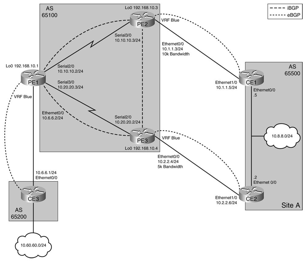
In Figure 7-7, site A has two routers, CE1 and CE2, advertising the prefix 10.8.8.0/24 to their connected provider edge routers, PE2 and PE3, respectively, through external BGP. PE2 and PE3 have a defined bandwidth on the interfaces connected to these CEs. The PE routers carry the BGP DMZ-link bandwidth from the BGP external neighbor through the BGP DMZ-link community. Example 7-31 shows the configuration to propagate the bandwidth attribute on PE2 and PE3.
BGP DMZ Link
Example 7-31 Modified Configuration on PE2 and PE3 to Carry BGP DMZ-Link Community
303-PE2#show run | b router bgp
router bgp 65100
 no synchronization
 bgp log-neighbor-changes
 neighbor 192.168.10.1 remote-as 65100
 neighbor 192.168.10.1 update-source Loopback0
 no auto-summary
 !
 address-family vpnv4
 neighbor 192.168.10.1 activate
 neighbor 192.168.10.1 send-community extended
 exit-address-family
 !
 address-family ipv4 vrf blue
 redistribute connected
 neighbor 10.1.1.5 remote-as 65500
 neighbor 10.1.1.5 activate
 neighbor 10.1.1.5 dmzlink-bw
 no auto-summary
 no synchronization
 exit-address-family
!
PE3-304#show run | b router bgp
router bgp 65100
 no synchronization
 bgp log-neighbor-changes
 neighbor 192.168.10.1 remote-as 65100
 neighbor 192.168.10.1 update-source Loopback0
 no auto-summary
 !
 address-family vpnv4
 neighbor 192.168.10.1 activate
 neighbor 192.168.10.1 send-community extended
 exit-address-family
 !
 address-family ipv4 vrf blue
 redistribute connected
 neighbor 10.2.2.6 remote-as 65500
 neighbor 10.2.2.6 activate
 neighbor 10.2.2.6 dmzlink-bw
 no auto-summary
 no synchronization
 exit-address-family
The output in Example 7-32 shows that the PE routers carry the bandwidth. The router expresses the DMZ-link bandwidth in kilobytes (KBps), whereas the interface bandwidth is in kilobits (kbps).
Example 7-32 Verifying Bandwidth Carried Through BGP
303-PE2#show ip bgp vpn vrf blue 10.8.8.0
BGP routing table entry for 100:100:10.8.8.0/24, version 13
Paths: (1 available, best #1, table blue)
 Advertised to update-groups:
   1
 65500
  10.1.1.5 (via blue) from 10.1.1.5 (10.8.8.5)
   Origin IGP, metric 0, localpref 100, valid, external, best
   Extended Community: RT:100:100
   DMZ-Link Bw 1250 kbytes

PE3-304#show ip bgp vpn vrf blue 10.8.8.0
BGP routing table entry for 100:100:10.8.8.0/24, version 6
Paths: (1 available, best #1, table blue)
 Advertised to update-groups:
   1
 65500
  10.2.2.6 (via blue) from 10.2.2.6 (10.8.8.6)
   Origin IGP, metric 0, localpref 100, valid, external, best
   Extended Community: RT:100:100
   DMZ-Link Bw 625 kbytes
PE3-304#
Before the availability of the iBGP load-sharing feature, Cisco IOS would only select one iBGP best path. For iBGP load sharing to be successful, by default, the routes must have equal attributes, such as weight, local preference, AS path, origin code, and IGP metric. If the attributes are not the same, the router does not use the path as a multiple path and only picks the best path.
In this case, PE1’s configuration allows utilization of both paths through iBGP load sharing, and the attributes are the equal. Therefore, PE1 receives the route and uses both paths through multipath configuration. PE1 uses the defined DMZ-link bandwidth locally because of the configured bgp dmzlink-bw command under the address family VPNv4.
Example 7-33 Configuring PE1 to Receive and Use the BGP-Carried Bandwidth
302-PE1#show run | b router bgp
router bgp 65100
 no synchronization
 bgp log-neighbor-changes
 neighbor 192.168.10.3 remote-as 65100
 neighbor 192.168.10.3 update-source Loopback0
 neighbor 192.168.10.4 remote-as 65100
 neighbor 192.168.10.4 update-source Loopback0
 no auto-summary
 !
 address-family vpnv4
 neighbor 192.168.10.3 activate
 neighbor 192.168.10.3 send-community extended
 neighbor 192.168.10.4 activate
 neighbor 192.168.10.4 send-community extended
 bgp dmzlink-bw
 exit-address-family
 !
 address-family ipv4 vrf blue
 neighbor 10.6.6.1 remote-as 65200
 neighbor 10.6.6.1 activate
 maximum-paths ibgp 2
 no auto-summary
 no synchronization
 exit-address-family
Router PE1 receives two paths, including the DMZ-link bandwidth, through the output shown in Example 7-34.
Example 7-34 BGP Verification That PE1 Receives Paths and Bandwidth
302-PE1#show ip bgp vpn vrf blue 10.8.8.0
BGP routing table entry for 100:100:10.8.8.0/24, version 11
Paths: (2 available, best #1, table blue)
Multipath: iBGP
 Advertised to update-groups:
   1
 65500
  192.168.10.3 (metric 65) from 192.168.10.3 (192.168.10.3)
   Origin IGP, metric 0, localpref 100, valid, internal, multipath, best
   Extended Community: RT:100:100
   DMZ-Link Bw 1250 kbytes
 65500
  192.168.10.4 (metric 65) from 192.168.10.4 (192.168.10.4)
   Origin IGP, metric 0, localpref 100, valid, internal, multipath
   Extended Community: RT:100:100
   DMZ-Link Bw 625 kbytes
302-PE1#
PE1 passes this DMZ-link bandwidth to the routing table and VRF table, as shown in Example 7-35. Notice that the traffic count is two for the path through 192.168.10.3 and one for the path through 192.168.10.4.
Example 7-35 Verifying BGP Unequal Load Sharing Through Routing and CEF Tables
302-PE1#show ip route vrf blue 10.8.8.0
Routing entry for 10.8.8.0/24
 Known via "bgp 65100", distance 200, metric 0
 Tag 65500, type internal
 Last update from 192.168.10.4 04:09:31 ago
 Routing Descriptor Blocks:
 * 192.168.10.3 (Default-IP-Routing-Table), from 192.168.10.3, 04:09:31 ago
   Route metric is 0, traffic share count is 2
   AS Hops 1, BGP network version 0
   Route tag 65500
  192.168.10.4 (Default-IP-Routing-Table), from 192.168.10.4, 04:09:31 ago
   Route metric is 0, traffic share count is 1
   AS Hops 1, BGP network version 0
   Route tag 65500
302-PE1#show ip cef vrf blue 10.8.8.0
10.8.8.0/24, version 82, epoch 0, per-destination sharing
0 packets, 0 bytes
 tag information set, all rewrites owned
  local tag: VPN route head
 via 192.168.10.3, 0 dependencies, recursive
  traffic share 2
  next hop 10.10.10.3, Serial2/0 via 192.168.10.3/32 (Default)
  valid adjacency
  tag rewrite with
    Recursive rewrite via 192.168.10.3/32, tags imposed {25}
 via 192.168.10.4, 0 dependencies, recursive
  traffic share 1
  next hop 10.20.20.4, Serial3/0 via 192.168.10.4/32 (Default)
  valid adjacency
  tag rewrite with
    Recursive rewrite via 192.168.10.4/32, tags imposed {18}
 0 packets, 0 bytes switched through the prefix
 tmstats: external 0 packets, 0 bytes
      internal 0 packets, 0 bytes
302-PE1#
Load Sharing Between P and P Devices
Sometimes network architects desire multiple links between the P and P devices to help distribute load. Different configurations are possible. Multiple links could exist between the same P devices, or multiple links could exist to different P devices. When going from one P device to another, the P device bases the forwarding decision on the MPLS label. With multiple paths, CEF is still the basis for populating the load-sharing table and deciding the ultimate path to a destination. When a P router with multiple outgoing equal-cost paths receives a packet with an MPLS label, it makes the load-sharing decision using the hash of the source and destination IP addresses as inputs in the CEF algorithm. The output of the hash determines which interface and label to use.
On a P router, using the show ip cef exact-route command is not applicable because it requires the presence of the destination IP addresses in the CEF table. As a quick, rough check of load sharing on a P router, an administrator can check the LFIB counters. However, this might not be accurate depending on the design. In later Cisco IOS code, such as IOS Release 12.0(28)S2, the show mpls forwarding-table labels command is available to check the path.
Table 7-11 describes the commands used to determine the CEF path.
Table 7-11 Commands to Determine the CEF Path for a Flow
| Device Function | Most IOS Routers | SUP720 |
| IP-to-IP routing | show ip cef exact-route | show mls cef exact-route |
| IP-to-label switching | show ip cef vrf | show mls cef exact-route |
| Label-to-label switching | show mpls forwarding-table labels exact-path ipv4 | — |
CEF and MPLS VPN Load-Sharing Platform Dependencies
You must consider some platform dependencies when doing load sharing in an MPLS VPN scenario. On Cisco 12000 series routers, each line card makes independent forwarding decisions using hardware-based CEF tables. Therefore, the route calculated in software and viewed using the show ip cef exact-route
Another point is that the Engine 4 MPLS load-sharing mechanism is different from other line cards. The hash uses the destination next-hop address to load-share on the E4 line card instead of the source-destination pair. Therefore, load sharing can occur across the links in the core based on egress PE loopback addresses in an MPLS VPN environment. On E4+, load sharing occurs based on the IP source and destination addresses on a per-flow basis and can be more granular.
Engine 3 only supports per-destination load sharing as an ingress card. For IP packets, the line card hardware can do a hash on the source and destination IP addresses to determine the egress interface. If an Engine 3 port is a VRF interface, the line card’s software instead of the hardware does the load-sharing hash. Therefore, the software selects the egress interface on a round-robin basis and programs the hardware in this case.
Originally, on a Cisco Catalyst 6500 with a SUP720, load sharing was available only in the IP-to-label and the label-to-IP directions for MPLS VPN. On a Catalyst 6500 with a SUP720 or a Cisco 7600 router that serves as a P router, the mpls load-balance per-label command allows use of the incoming label for load sharing. With this command, load sharing occurs based on the topmost incoming label in the stack that the packet arrives with. So, for example, if the outgoing path is an equal-cost path, load sharing will occur using the top IGP label with this feature enabled.
Summary
This chapter reviews some of common CEF issues seen across various Cisco platforms. However, this is not an exhaustive examination of CEF troubleshooting in an MPLS VPN environment across all Cisco platforms. This chapter demonstrates some key elements that you should examine when troubleshooting a difficult MPLS VPN problem regarding CEF. It also illustrates that sometimes the basic issue is that the routes are not in the routing table in the beginning. Hence, CEF or the LFIB will not know about the multiple paths. This chapter also introduces some of the BGP and MPLS features to allow multiple paths to be known through CEF. However, many features are available to gain the desired results.
References
Asati, R., Troubleshooting MPLS VPN Networks, Networkers 2004.
Cisco, MPLS Virtual Private Networks (VPNs).
Cisco, How to Troubleshoot the MPLS VPN.
Cisco, Cisco IOS MPLS VPN Q & A. (This link requires Cisco.com registration.)
Cisco, Troubleshooting LSP Failure in MPLS VPN.
Cisco, Cisco 12000 Series Internet Router Architecture: Line Card Design.
Cisco, BGP Multipath Load Sharing for Both eBGP and iBGP in an MPLS-VPN.
Cisco, Load Sharing IP Packets over More Than Six Parallel Paths.
Cisco, Load Balancing in MPLS VPN Environments.
Cisco, MPLS FAQ for Beginners.
Cisco, Configuring Multiprotocol Label Switching on the Optical Services Module.
Cisco, Troubleshooting Cisco Catalyst 6000/6500 Switches, Networkers 2004.
Cisco, Cisco Catalyst 6500 Switch Architecture, Networkers 2004.
Cisco, Packet Forwarding and Operation of Mid to High End Routers and Switches, Networkers 2004.
Copyright © 2007 Pearson Education. All rights reserved.