The most commonly used categories of diagnostic tools used within Cisco IOS are show and debug commands. Throughout the course of this chapter, we will use variations of these two command sets to diagnose issues commonly found within Cisco IOS. As we’ve discussed, there are detailed steps that occur during the formation of Internet Security Association and Key Management Protocol (ISAKMP) and IPsec negotiation between two IPsec VPN endpoints. We will examine common errors in these steps through execution of the following debugging commands within IOS:
debug crypto isakmp
debug crypto IPsec
Additionally, we will explore several show commands necessary to uncover common errors and performance issues related to the negotiate of IPsec VPN tunnels, including fragmentation/maximum transmission unit (MTU) issues, quality of service (QoS) issues, Network Address Translation (NAT) issues, and issues relating to recursive routing. A subset of the commands we will discuss to address these issues includes:
show crypto isakmp sa
show crypto isakmp sa nat
show crypto IPsec sa
show crypto engine connections active
show crypto engine connections dropped-packet
show crypto engine connections flow
show crypto engine qos
Common Configuration Issues with IPsec VPNs
There are many parameters and features to understand when deploying IPsec VPNs. In this section, we will discuss configuration issues presented when one or more IPsec VPN gateways are configured incorrectly. After discussing the nature of each of the above commonly experienced IPsec VPN configuration issues, we will discuss the methods used to effectively diagnose and remedy these issues.
IKE SA Proposal Mismatches
Unless IPsec session keys are manually defined, two crypto endpoints must agree upon an ISAKMP policy to use when negotiating the secure Internet Key Exchange (IKE) channel, or ISAKMP security association (SA). As such, when two VPN endpoints fail to agree upon a usable ISAKMP policy, IPsec SA negotiation cannot initiate, and traffic will continue to flow unencrypted.
Figure 2-24 and Figure 2-25 provide a brief description of ISAKMP policy negotiation process in main mode and aggressive mode respectively and the involved configuration on two VPN endpoints. Also remember from our discussions in Chapter 2 that ISAKMP policies are listed in order of priority (the lower number being the highest priority). The initiator will offer the highest priority proposal, and the responder will search its locally configured ISAKMP policies for a match. If there are none, the initiator will propose the next highest ISAKMP policy and define its local configuration. This process will continue until the initiator has no proposals left to offer the responder. The result, in this case, would be an ISAKMP SA proposal mismatch. Using the configurations provided in Example 4-1 and Example 4-2, Router_A and Router_B will attempt to form an IKE SA between one another using the topology illustrated in Figure 4-1.
ISAKMP SA Negotiation Resulting in ISAKMP Proposal Mismatch
Example 4-1 provides the ISAKMP policies configured for Router_A in Figure 4-1. Note that, in this configuration, there are no ISAKMP proposals configured that match those configured on Router_B in Example 4-2.
Example 4-1 Crypto ISAKMP Policy Definition for Router_A in Figure 4-1 (Mismatch with Router_B, Example 4-2)
Router_A#show crypto isakmp policy

Global IKE policy
Protection suite of priority 10
    encryption algorithm:  Three key triple DES
    hash algorithm:     Message Digest 5
    authentication method: Pre-Shared Key
    Diffie-Hellman group:  #2 (1024 bit)
    lifetime:        86400 seconds, no volume limit
Protection suite of priority 20
    encryption algorithm:  DES - Data Encryption Standard (56 bit keys).
    hash algorithm:     Secure Hash Standard
    authentication method: Pre-Shared Key
    Diffie-Hellman group:  #2 (1024 bit)
    lifetime:        86400 seconds, no volume limit
Protection suite of priority 30
    encryption algorithm:  AES - Advanced Encryption Standard (128 bit keys).
    hash algorithm:     Secure Hash Standard
    authentication method: Rivest-Shamir-Adleman Signature
    Diffie-Hellman group:  #1 (768 bit)
    lifetime:        86400 seconds, no volume limit
Default protection suite
    encryption algorithm:  DES - Data Encryption Standard (56 bit keys).
    hash algorithm:     Secure Hash Standard
    authentication method: Rivest-Shamir-Adleman Signature
    Diffie-Hellman group:  #1 (768 bit)
    lifetime:        86400 seconds, no volume limit
Example 4-2 provides the ISAKMP policy configuration on Router_B of Figure 4-1. Router_B will use this policy when building an ISAKMP SA to Router_A, whose ISAKMP policy is provided in Example 4-1. Because Router_B’s ISAKMP configuration contains no matching proposals with Router_A’s configuration provided in Example 4-1, ISAKMP negotiation will fail.
Example 4-2 Crypto ISAKMP Policy Definition for Router_B in Figure 4-1 (Mismatch with Router_B, Example 4-1)
Router_B#show crypto isakmp policy

Global IKE policy
Protection suite of priority 10
    encryption algorithm:  AES - Advanced Encryption Standard (128 bit keys).
    hash algorithm:     Message Digest 5
    authentication method: Pre-Shared Key
    Diffie-Hellman group:  #5 (1536 bit)
    lifetime:        86400 seconds, no volume limit
Protection suite of priority 20
    encryption algorithm:  Three key triple DES
    hash algorithm:     Message Digest 5
    authentication method: Rivest-Shamir-Adleman Signature
    Diffie-Hellman group:  #1 (768 bit)
    lifetime:        86400 seconds, no volume limit
Protection suite of priority 30
    encryption algorithm:  DES - Data Encryption Standard (56 bit keys).
    hash algorithm:     Secure Hash Standard
    authentication method: Pre-Shared Key
    Diffie-Hellman group:  #2 (1024 bit)
    lifetime:        86400 seconds, no volume limit
Default protection suite
    encryption algorithm:  DES - Data Encryption Standard (56 bit keys).
    hash algorithm:     Secure Hash Standard
    authentication method: Rivest-Shamir-Adleman Signature
    Diffie-Hellman group:  #1 (768 bit)
    lifetime:        86400 seconds, no volume limit
The following numbered sequence of events describes the ISAKMP proposal mismatch between the configurations provided in Example 4-1 for Router_A in Figure 4-1 and Example 4-2 for Router_B in Figure 4-1.
Router A sends its configured ISAKMP policies 10, 20, and 30 to Router B.
Router B checks policy 10 obtained in step 1 against its own configured policies, beginning with the lowest numbered policy and ending with the highest.
If Router B does not find a match in step 2, it checks policy 20 obtained in step 1 against its own configured policies, starting with the lowest numbered and ending with the highest.
If Router B does not find a match in step 3, it checks policy 30 obtained in step 1 against its own configured policies, starting with the lowest numbered and ending with the highest.
If Router B does not find a match in step 4, then a proposal mismatch has occurred, and the Phase 1 negotiation times out.
In order to confirm that IKE proposal mismatches have occurred in an IPsec VPN tunnel negotiation, we will inspect the output of the ISAKMP SA negotiation between Routers A and B. Routers A and B are using preshared IKE authentication in a site-to-site VPN, but have not been configured with matching ISAKMP policies. We will execute the command debug crypto isakmp on routers A and B to highlight that an IKE proposal mismatch is indeed the cause of ISAKMP SA negotiation failure. Example 4-3 displays debugging output as ISAKMP policies proposed by Router_A are checked against locally configured policies on Router_B.
In the diagnostic output shown in Example 4-3, Router_B checks proposals sent from Router_A for potential matches. Router_B begins by checking the ISAKMP proposals sent from Router_A against its own configured ISAKMP proposals. It does this by checking all of the proposals received (starting with lowest numbered and ending with highest) against favored policy (lowest numbered). If there are no matches, it checks the received policies in the same order against its next-lowest-numbered policy. This process continues until a match is found or all policies have been checked and no match has been found. In this specific proposal, the encryption proposed for encrypting the IKE channel does not match (see Examples 4-2 and 4-3 for ISAKMP proposal information for Router_A and Router_B), and Router B continues to check other offered proposals against its locally configured ISAKMP policies. Example 4-3, line 12, confirms that a proposal mismatch has occurred. Router_B finds that no ISAKMP proposals sent from Router_A match its own configured ISAKMP policies and therefore deletes the Phase1 SA and Phase1 negotiation times out on Router_A, as confirmed in Example 4-3, line 18.
Example 4-3 Isolating IKE Proposal Mismatches on the Initiating VPN Endpoint (Router A)
1 Router_B#debug crypto isakmp
2 Crypto ISAKMP debugging is on
3 !
4 !
5 *Feb 16 12:11:02.379: ISAKMP:(0:0:N/A:0):Checking ISAKMP transform 1 against priority 10 policy
6 *Feb 16 12:11:02.379: ISAKMP:   encryption 3DES-CBC
7 *Feb 16 12:11:02.379: ISAKMP:   hash MD5
8 *Feb 16 12:11:02.379: ISAKMP:   default group 2
9 *Feb 16 12:11:02.379: ISAKMP:   auth pre-share
10 *Feb 16 12:11:02.379: ISAKMP:   life type in seconds
11 *Feb 16 12:11:02.379: ISAKMP:   life duration (VPI) of 0x0 0x1 0x51 0x80
12 *Feb 16 12:11:02.379: ISAKMP:(0:0:N/A:0):Encryption algorithm offered does not match policy!
13 !
14 !
15 *Feb 16 12:11:02.379: ISAKMP:(0:0:N/A:0):no offers accepted!
16 *Feb 16 12:11:02.379: ISAKMP:(0:0:N/A:0): phase 1 SA policy not acceptable! (local 200.0.0.2 remote 200.0.0.1)
17 *Feb 16 12:11:02.379: ISAKMP:(0:0:N/A:0):peer does not do paranoid keepalives.
18 *Feb 16 12:11:02.379: ISAKMP:(0:0:N/A:0):deleting SA reason "Phase1 SA policy proposal not accepted" state (R) MM_NO_STATE (peer 200.0.0.1)
Until the two endpoints can agree on an ISAKMP policy to use when securing the IKE channel and negotiating a Diffie-Hellman key to use when encrypting the IKE exchanges and in the IPsec transform, IPsec VPN tunnel negotiation cannot continue. Another task that must be performed successfully for IPsec VPN tunnel negotiation to continue is IKE authentication.
IKE Authentication Failures and Errors
Recall from our previous discussions that, in Cisco IOS, there are three methods offered to authenticate peers wanting to negotiate an ISAKMP SA: preshared keys (PSKs), RSA signatures, or RSA encryption. As we had discussed in Chapter 2, all three authentication methods have distinct elements used when authenticating IKE Peers. We will discuss common IKE authentication failure issues within the context of each of these three authentication methods.
IKE Authentication Errors and PSKs
There are two conditions that must be met for two IPsec VPN endpoints to authenticate each other using IKE PSKs. First, matching keys must be configured on the two endpoints. Second, the endpoints must be configured to share these keys with the correct peer. Router_A and Router_B are now configured with matching ISAKMP policies for Phase 1 negotiation, but still have problems preventing them from authenticating one another. We will examine debugging output on the routers in Figure 4-2 to highlight authentication failures directly attributable to mismatched keys and mismatched peers.
Example 4-4 provides the configuration of Router_A in Figure 4-2. Note that, unlike Router_A’s configuration in Figure 4-1, Router_A is now configured with an ISAKMP policy that contains a matching proposal (Example 4-4, priority 30) with Router_B (Example 4-5, priority 10). In this case, however, IKE will still fail to negotiate due to a mismatched PSK on Router_A (Example 4-4, line 32) and Router_B (Example 4-5, line 32).
Example 4-4 Mismatched IKE PSK on Router_A (Corresponds with Mismatched Key for Router_B in Example 4-5)
1  Router_A#show crypto isakmp policy
2
3  Global IKE policy
4  #<--ISAKMP Policy 10 Matches Router_B's ISAKMP Proposal 30 (Example 4-5 below)-->
5  Protection suite of priority 10
6      encryption algorithm:  Three key triple DES
7      hash algorithm:     Message Digest 5
8      authentication method: Pre-Shared Key
9      Diffie-Hellman group:  #2 (1024 bit)
10      lifetime:        86400 seconds, no volume limit
11 Protection suite of priority 20
12     encryption algorithm:  DES - Data Encryption Standard (56 bit keys).
13     hash algorithm:     Secure Hash Standard
14     authentication method: Pre-Shared Key
15     Diffie-Hellman group:  #2 (1024 bit)
16     lifetime:        86400 seconds, no volume limit
17 Protection suite of priority 30
18     encryption algorithm:  AES - Advanced Encryption Standard (128 bit keys).
19     hash algorithm:     Secure Hash Standard
20     authentication method: Pre-Shared Key
21     Diffie-Hellman group:  #5 (1536 bit)
22     lifetime:        86400 seconds, no volume limit
23 Default protection suite
24     encryption algorithm:  DES - Data Encryption Standard (56 bit keys).
25     hash algorithm:     Secure Hash Standard
26     authentication method: Rivest-Shamir-Adleman Signature
27     Diffie-Hellman group:  #1 (768 bit)
28     lifetime:        86400 seconds, no volume limit
29 Router_A#show crypto isakmp key
30 Keyring        Hostname/Address          PSK
31
32 default        200.0.0.2             tarheels
Example 4-5 provides the configuration of Router_B in Figure 4-2. Note that Router_B’s ISAKMP proposal listed with priority 10 (Example 4-4, lines 5-10) will match Router_A’s proposal listed with priority 30 (Example 4-4, lines 17-22). However, IKE will still fail because of mismatched PSKs on Router_A (Example 4-4, line 32) and Router_B (Example 4-5, line 32).
Example 4-5 Mismatched IKE PSK on Router_B (Corresponds with Mismatched Key for Router_A in Example 4-4)
1  Router_B#show crypto isakmp policy
2
3  Global IKE policy
4  Protection suite of priority 10
5      encryption algorithm:  AES - Advanced Encryption Standard (128 bit keys).
6      hash algorithm:     Secure Hash Standard
7      authentication method: Pre-Shared Key
8      Diffie-Hellman group:  #5 (1536 bit)
9      lifetime:        86400 seconds, no volume limit
10 Protection suite of priority 20
11     encryption algorithm:  Three key triple DES
12     hash algorithm:     Message Digest 5
13     authentication method: Rivest-Shamir-Adleman Signature
14     Diffie-Hellman group:  #1 (768 bit)
15     lifetime:        86400 seconds, no volume limit
17  #<--ISAKMP Policy 30 Matches Router_A's ISAKMP Proposal 10 (Example 4-4 above)-->
17 Protection suite of priority 30
18     encryption algorithm:  AES - Advanced Encryption Standard (128 bit keys).
19     hash algorithm:     Secure Hash Standard
20     authentication method: Pre-Shared Key
21     Diffie-Hellman group:  #2 (1024 bit)
22     lifetime:        86400 seconds, no volume limit
23 Default protection suite
24     encryption algorithm:  DES - Data Encryption Standard (56 bit keys).
25     hash algorithm:     Secure Hash Standard
26     authentication method: Rivest-Shamir-Adleman Signature
27     Diffie-Hellman group:  #1 (768 bit)
28     lifetime:        86400 seconds, no volume limit
29 Router_A#show crypto isakmp key
30 Keyring        Hostname/Address          PSK
31
32 default        200.0.0.1             bluedevils
Mismatched Keys
Note that, in Example 4-4 and Example 4-5, the Router_A fails to negotiate an IKE SA due to mismatched PSKs. The diagnostic output provided in Example 4-6, line 13, confirms that the two crypto peers have agreed on an IKE proposal. However, Example 4-6, line 18, confirms that the SA fails negotiation due to a PSK mismatch.
Example 4-6 PSK Authentication Failure Between Two IKE Endpoints
1 Router_A#debug crypto isakmp
2 Crypto ISAKMP debugging is on
3 !
4 !
5 *Feb 16 14:20:44.991: ISAKMP (0:1): Checking ISAKMP transform 1 against priority 30 policy
6 *Feb 16 14:20:44.991: ISAKMP:   encryption AES-CBC
7 *Feb 16 14:20:44.991: ISAKMP:   keylength of 128
8 *Feb 16 14:20:44.991: ISAKMP:   hash SHA
9 *Feb 16 14:20:44.991: ISAKMP:   default group 5
10 *Feb 16 14:20:44.991: ISAKMP:   auth pre-share
11 *Feb 16 14:20:44.991: ISAKMP:   life type in seconds
12 *Feb 16 14:20:44.995: ISAKMP:   life duration (VPI) of 0x0 0x1 0x51 0x80
13 *Feb 16 14:20:44.995: ISAKMP (0:1): atts are acceptable. Next payload is 0
14 !
15 !
16 *Feb 16 14:20:45.319: ISAKMP (0:1): received packet from 200.1.1.2 dport 500 sport 500 Global (I) MM_KEY_EXCH
17 *Feb 16 14:20:45.319: ISAKMP: reserved not zero on NOTIFY payload!
18 *Feb 16 14:20:45.319: %CRYPTO-4-IKMP_BAD_MESSAGE: IKE message from 200.0.0.2    failed its sanity check or is malformed
Mismatched Peer Addresses in IKE PSK Definition
As we have discussed, there are two elements to troubleshoot in a PSK authentication scheme. Thus far, we’ve covered IKE failure due to PSK mismatches. Now, let’s turn our attention to IKE issues surrounding peering specification on PSKs. Suppose that, in Figure 4-2, Router_A decides to source all peering sessions from its loopback interface (loopack 1, ip=201.0.0.1/32).
The default behavior of an IOS IPsec endpoint is to source the IPsec VPN tunnel from the IP address of the physical interface where the crypto map is applied. Example 4-7 changes IPsec peering behavior from the router’s default settings by instructing the router to use a loopback interface for sourcing the IPsec VPN tunnel.
Example 4-7 Router_A Sources IPsec VPNs from Its Loopback1 Interface (201.0.0.1)
The administrators of Router_B must make two basic changes to accommodate this change on Router_A. They must first change their IPsec peering definition in their crypto map to point to Router_A’s new source (its loopback address, 201.0.0.1). This change is illustrated in the configuration fragment provided in Example 4-8.
Example 4-8 Necessary Peering Changes Required on Router_B
Assume, though, that the administrators of Router_B did not correctly modify the peer address on their PSK statement to accurately reflect the changes on Router_A. This too would result in an IKE authentication failure, ultimately causing IPsec VPN tunnel negotiation to stop before Phase 1 negotiation can complete. The debugging output in Example 4-9 can be inspected to confirm that, although IKE PSKs do match, they are not being shared with the correct peers. Due to the fact that the IPsec peer has been updated to point to 201.0.0.1 (Example 4-8), the IKE engine will try to look for a key to use with that peer. In this case, the case described in Example 4-9, the IKE PSK statement has not been updated, and the IKE Phase 1 negotiation subsequently fails to kick off. Note that the peer statement in Example 4-8 has been changed to 201.0.0.1, but the IKE PSK statement is still 200.0.0.1. The diagnostic output provided in Example 4-9 confirms this error, as IKE cannot find a matching key to use with the new IPsec peer statement in the crypto map (201.0.0.1).
Example 4-9 IKE Authentication Failure Due to PSKs Not Being Shared with the Correct Peer Addresses
!
!
*Feb 16 14:30:00.595: ISAKMP:(0:0:N/A:0):Can not start Aggressive mode, trying Main mode.
*Feb 16 14:30:00.595: ISAKMP: Looking for a matching key for 201.0.0.1 in default
*Feb 16 14:30:00.595: ISAKMP:(0:0:N/A:0):No pre-shared key with 201.0.0.1!
!
Solving Key Mismatch and Peer Mismatch Issues on Router_A and Router_B
Indeed, the administrators of Router_B realize that they had made a mistake in selecting “bluedevils” as the IKE PSK and fix the problem. Additionally, all of the ISAKMP address information on PSK definitions on Router_A and Router_B have changed to be consistent. Now that Router_A and Router_B can agree on an ISAKMP policy and PSK with the appropriate peering information intact, an IKE can successfully be negotiated as evidenced by debugging output from IKE Phase 1 negotiation on Router_B (Example 4-10). Example 4-10, line 13, confirms that the two crypto peers have agreed on an ISAKMP proposal, and Example 4-10 line 22 confirms that the SA has been authenticated. Once Phase 1 negotiation is complete, the ISAKMP SA can be verified without debugging, using show commands, as illustrated in Example 4-10, lines 23–25.
Example 4-10 Successful IKE Authentication Using PSKs (Router_B)
1 Router_B#debug crypto isakmp
2 Crypto ISAKMP debugging is on
3 !
4 !
5 *Feb 16 14:44:55.063: ISAKMP (0:1): Checking ISAKMP transform 1 against priority 30 policy
6 *Feb 16 14:44:55.063: ISAKMP:   encryption AES-CBC
7 *Feb 16 14:44:55.063: ISAKMP:   keylength of 128
8 *Feb 16 14:44:55.063: ISAKMP:   hash SHA
9 *Feb 16 14:44:55.063: ISAKMP:   default group 5
10 *Feb 16 14:44:55.063: ISAKMP:   auth pre-share
11 *Feb 16 14:44:55.063: ISAKMP:   life type in seconds
12 *Feb 16 14:44:55.063: ISAKMP:   life duration (VPI) of 0x0 0x1 0x51 0x80
13 *Feb 16 14:44:55.063: ISAKMP (0:1): atts are acceptable. Next payload is 3
14 !
15 !
16 *Feb 16 14:44:55.431: ISAKMP (0:1): SA authentication status:
17     Authenticated
18 *Feb 16 14:44:55.431: ISAKMP (0:1): Process initial contact,
19 bring down existing phase 1 and 2 SA's with local 200.1.1.2 remote 201.0.0.1 remote port 500
20 *Feb 16 14:44:55.431: ISAKMP (0:1): SA authentication status:
21     authenticated
22 *Feb 16 14:44:55.431: ISAKMP (0:1): SA has been authenticated with 201.0.0.1
23 Router_B#sh crypto isakmp sa
24 dst       src       state     conn-id slot
25 200.0.0.2    201.0.0.1    QM_IDLE       1  0
IKE Authentication Errors with RSA Encryption
As with the PSK method of authenticating IKE peers, IKE authentication failures using RSA encryption are commonly attributed to two categories—mismatched keys or mismatched peers. As such, we will begin our RSA encryption discussion with a scenario in which RSA public keys are not matched correctly. Remember that RSA encryption algorithm is asymmetric, consisting of two keys—the public/decryption key and the private/encryption key. If the incorrect keys are provided to IPsec VPN peers using RSA Encryption, Phase 1 negotiation will time out due to IKE authentication errors. The endpoints in Figure 4-3 are set up to do RSA encryption for IKE authentication.
IKE Authentication Failure—Mismatched RSA Public Keys
Example 4-11 provides the RSA key configuration of Router_A in Figure 4-3. The router uses RSA encryption as the IKE authentication method, requiring a public (encryption) key and a private (decryption) key to authenticate the SA. Router_A’s private key is manually generated, and is listed in Example 4-11, lines 3-9. The administrator of Router_A has manually entered Router_B’s encryption key, as listed in Example 4-11, lines 20-29.
Example 4-11 Router_A’s (Figure 4-3) RSA Key Configuration for IKE SA Establishment with Router_B
Example 4-12 provides the RSA key configuration of Router_B in Figure 4-3. Note that Router B has mistakenly been configured with Router_A’s private key, rather than its public key.
Example 4-12 Router_B’s (Figure 4-3) RSA Key Configuration for IKE SA Establishment with Router_A
Example 4-13, line 5, confirms that ISAKMP SA negotiation is initiated with RSA Encryption for authentication. Output from Example 4-13, line 8, indicates that IKE messages cannot be decrypted, because Router_B is mistakenly using Router_A’s decryption key for encrypting IKE messages to Router_A, rather than using Router_A’s proper encryption key to do so. Example 4-13, lines 19-40, illustrate that the same key misconfiguration on Router_A is causing IKE SA authentication to fail on Router_B for the same reasons it failed earlier on Router_A.
Example 4-13 Troubleshooting IKE Authentication Failures with RSA Encryption
1 Router_A#debug crypto isakmp
2 Crypto ISAKMP debugging is on
3 !
4 !
5 *Feb 17 10:58:20.066: ISAKMP (0:1): SA is doing RSA encryption authentication using id type ID_IPV4_ADDR
6 !
7 !
8 *Feb 17 10:58:20.554: %CRYPTO-6-IKMP_CRYPT_FAILURE: IKE (connection id 1) unable to decrypt (w/RSA private key) packet
9 !
10 !
11 *Feb 17 10:58:41.706: ISAKMP (0:1): retransmitting phase 1 MM_SA_SETUP...
12 *Feb 17 10:58:41.706: ISAKMP (0:1): incrementing error counter on sa: retransmit phase 1
13 !
14 !
15 *Feb 17 10:59:19.918: ISAKMP (0:1): deleting SA reason "gen_IPsec_isakmp_delete but doi isakmp" state (I) MM_SA_SETUP (peer 200.0.0.2) input queue 0
16 *Feb 17 10:59:19.918: ISAKMP (0:1): Input = IKE_MESG_INTERNAL, IKE_PHASE1_DEL
17 *Feb 17 10:59:19.918: ISAKMP (0:1): Old State = IKE_I_MM3 New State = IKE_DEST_SA
18
19 Router_B#debug crypto isakmp
20 Crypto ISAKMP debugging is on
21 !
22 !
23 *Feb 17 10:01:10.930: ISAKMP:(0:1:SW:1):SA is doing RSA encryption authentication using id type ID_IPV4_ADDR
24 !
25 !
26 *Feb 17 10:01:21.658: ISAKMP:(0:1:SW:1): retransmitting phase 1 MM_KEY_EXCH
27 *Feb 17 10:01:21.658: ISAKMP:(0:1:SW:1): sending packet to 200.1.1.1 my_port 500 peer_port 500 (R) MM_KEY_EXCH
28 !
29 !
30 *Feb 17 10:01:55.466: ISAKMP: quick mode timer expired.
31 *Feb 17 10:01:55.466: ISAKMP:(0:1:SW:1):src 200.0.0.1 dst 200.0.0.2, SA is not authenticated
32 *Feb 17 10:01:55.466: ISAKMP:(0:1:SW:1):peer does not do paranoid keepalives.
33 !
34 !
35 *Feb 17 10:01:55.466: ISAKMP:(0:1:SW:1):deleting SA reason "QM_TIMER expired" state (R) MM_KEY_EXCH (peer 200.0.0.1)
36 *Feb 17 10:01:55.466: ISAKMP:(0:1:SW:1):deleting SA reason "QM_TIMER expired" state (R) MM_KEY_EXCH (peer 200.1.1.1)
37 *Feb 17 10:01:55.466: ISAKMP: Unlocking IKE struct 0x65C405A8 for isadb_mark_sa_deleted(), count 0
38 *Feb 17 10:01:55.466: ISAKMP: Deleting peer node by peer_reap for 200.1.1.1: 65C405A8
39 *Feb 17 10:01:55.466: ISAKMP:(0:1:SW:1):Input = IKE_MESG_INTERNAL, IKE_PHASE1_DEL
40 *Feb 17 10:01:55.466: ISAKMP:(0:1:SW:1):Old State = IKE_R_MM4 New State = IKE_DEST_SA
Cisco IOS VPN endpoints can be instructed to use certain RSA public keys with certain peers, a similar functionality to standard PSK authentication. As such, it is important that each VPN endpoint is using the correct key for the correct peer. Consider once again the situation in which the administrators of Router_A choose to source the VPN tunnel endpoint from their loopback1 (201.0.0.1) interface. The administrators of Router_B have fixed the mismatching key problem in Example 4-11 through Example 4-13, and have updated their IPsec configuration to peer with Router_A’s loopback address. However, they have not updated the address that ISAKMP should use when authenticating the IKE channel with Router_B’s public/encryption key (see configurations listed in Figure 4-4). Therefore, Router_B cannot select the appropriate public key to authenticate the IKE channel with Router_A. Once again, this leads to an IKE Authentication error, which eventually causes ISAKMP SA negotiation to time out.
Example 4-15 provides the RSA key configuration for Router_B in Figure 4-4. Note that, although the public and private keys have been correctly configured on Router_A and Router_B, Router_B is not configured with the correct peering information in its encryption key settings to be used with Router_A. This peer mismatch is illustrated in Example 4-15, lines 22-23.
Example 4-15 Router_B RSA Encryption Key Peer Mismatch with Router_A in Figure 4-4 (Router_A Configuration Provided in Example 4-14)
Once the configuration on Router_B (Example 4-15, lines 22-23) has been updated to use Router_A’s public key with Router_A’s new peering information (lo1=201.0.0.1), then the ISAKMP SA can be negotiated successfully using RSA Encryption as confirmed in Example 4-16.
Example 4-16 Updated Peer Configuration on Router_B, and ISAKMP SA Confirmation
1 Router_B#sh run
2 Building configuration...
3 crypto key pubkey-chain rsa
4  addressed-key 201.0.0.1
5  address 201.0.0.1
6  key-string
7   305C300D 06092A86 4886F70D 01010105 00034B00 30480241 00BF6D28 71EE1FF2
8   415E4001 23F4D08C 62DFEAA8 4C0682A4 39D66B5D DC275EAB C95DE5A4 1C87700B
9   4A6AB4F3 8ACFFE4D 6B409C93 6BB3DAE3 D7D13398 3C48C7A1 B5020301 0001
10  quit
11
12 Router_B#ping
13 !
14 !
15 Sending 5, 100-byte ICMP Echos to 202.1.1.1, timeout is 2 seconds:
16 Packet sent with a source address of 202.2.2.1
17 .!!!!
18 Success rate is 80 percent (4/5), round-trip min/avg/max = 40/43/44 ms
19 *Feb 17 11:21:41.570: %CRYPTO-5-SESSION_STATUS: Crypto tunnel is UP . Peer 201.0.0.1:500    Id: 201.0.0.1
20 Router_B#show crypto isakmp sa
21 dst       src       state     conn-id slot
22 201.0.0.1    200.1.1.2    QM_IDLE       1  0
23 Router_B#show crypto key pubkey-chain rsa
24 Codes: M - Manually configured, C - Extracted from certificate
25
26 Code Usage     IP-Address/VRF     Keyring     Name
27 M  General    201.0.0.1       default
Note – In the preceding examples pertaining to RSA encryption, Router_A (512 bit-mod) and Router_B (1024-bit mod) have been using mismatched key modulus. This will not cause IKE authentication errors, but does not provide the same strength in authentication as using 1024-bit keys on both sides.
Last, it is important to note that the configurations above use IP addresses (addressed-key) selecting public keys to use with their corresponding peer. Alternately, administrators can use hostnames to identify peers, instead of IP addresses. When using hostnames, administrators must verify that the hostname can be resolved to an IP address via DNS or manually using the ip host [ip-address] [hostname] command in the local router configuration. Additionally, each peer using a hostname for ISAKMP identification must be instructed to do so using the crypto isakmp identity [hostname] command, as the default is use of the IP address associated with the physical interface where the crypto map is applied.
IKE Authentication Errors with RSA Signatures
As we’ll discuss later in Chapter 11, the dynamics of authentication change dramatically when RSA signatures are used. Until now, we’ve discussed IKE SA authentication methods that require direct key exchange between crypto endpoints, including both IKE PSK and RSA Encrypted Nonce methods of IKE authentication. Now we will discuss the RSA Signatures method of IKE SA authentication, in which both endpoints are authenticated indirectly using a centralized trusted resource, a Certificate Authority (CA), during Phase 1 negotiation. As such, our focus will not be on endpoint-endpoint authentication and peering, but instead will explore common IKE authentication issues attributable to endpoint-CA operation:
Authenticating the CA and Obtaining the CA Certificate
Enrolling with the CA and Obtaining Public Key Certificates
We will examine debugs and diagnostics for each of these processes using the topology in Figure 4-5, as Routers A and B obtain certificates from IOS_CAROOT needed for IKE authentication using RSA Signatures. It has been confirmed that Router_A and Router_B can reach the CA.
Troubleshooting IKE Authentication Errors with RSA Signatures
Example 4-17 provides the configuration for Router_A in Figure 4-5. We will use this configuration while troubleshooting and validating IKE SA authentication with RSA Signatures later in this chapter.
Example 4-17 RSA Signatures Configuration on Router_A (Figure 4-5)
Router_A#show crypto ca certificates
Certificate
 Status: Available
 Certificate Serial Number: 03
 Certificate Usage: General Purpose
 Issuer:
  cn=IOS_CAROOT
 Subject:
  Name: Router_A.cisco.com
  IP Address: 192.168.1.1
  Serial Number: 01C2F27F
  serialNumber=1C2F27F+ipaddress=192.168.1.1+hostname=Router_A.cisco.com
 Validity Date:
  start date: 10:12:45 UTC Feb 24 2005
  end  date: 10:12:45 UTC Feb 24 2006
  renew date: 00:00:00 UTC Jan 1 1970
 Associated Trustpoints: IOS_CAROOT

CA Certificate
 Status: Available
 Certificate Serial Number: 01
 Certificate Usage: Signature
 Issuer:
  cn=IOS_CAROOT
 Subject:
  cn=IOS_CAROOT
 Validity Date:
  start date: 09:06:11 UTC Feb 24 2005
  end  date: 09:06:11 UTC Feb 24 2008
 Associated Trustpoints: IOS_CAROOT

Router_A#show crypto key mypubkey rsa
% Key pair was generated at: 10:11:30 UTC Feb 24 2005
Key name: Router_A.cisco.com
 Usage: General Purpose Key
 Key is not exportable.
 Key Data:
 30819F30 0D06092A 864886F7 0D010101 05000381 8D003081 89028181 00AF2FC9
 1919ECF1 DE24C37D 796658E2 2B186600 98EB5CE3 AE0E53FE B1F736EA CE417989
 F3029E25 594B9BCB 30DD0A2D 799814B1 555071FE BFB081E1 80548F91 3021F997
 0FBC0B62 4A6284A4 22175B89 4D5C00B2 4DE6F657 F6CA00DA E8629294 413487F6
 6AB72BAF 071F4C63 CD813C3A 8925B95D F3DE265C CCFA3AA5 C38386DA 25020301 0001
% Key pair was generated at: 10:11:31 UTC Feb 24 2005
Key name: Router_A.cisco.com.server
 Usage: Encryption Key
 Key is exportable.
 Key Data:
 307C300D 06092A86 4886F70D 01010105 00036B00 30680261 00C7CE18 CD11DBAE
 6FE6999B 15E81063 998CD039 91677AAD 9E310C38 9CF10010 EE3BBD5C 574837E8
 08098084 D1F09C7D 9143F22C 6684AAA5 9B518676 AB205A9B 2681B77A 24E69ABA
 734AB29C 28D4A672 4C93B3B4 DE27CB77 FF0DBBF0 2A5ABF1F AF020301 0001

Router_A#show crypto key pubkey-chain rsa
Codes: M - Manually configured, C - Extracted from certificate

Code Usage     IP-Address/VRF     Keyring     Name
C  Signing               default     X.500 DN name:
               cn=IOS_CAROOT

C  Signing   192.168.2.1/      default     Router_B.cisco.com
Example 4-18 provides the configuration for Router_B in Figure 4-5. We will use this configuration while troubleshooting and validating IKE SA authentication with RSA Signatures later in this chapter.
Example 4-18 RSA Signatures Configuration on Router_B (Figure 4-5)
Router_B#show crypto ca certificates
Certificate
 Status: Available
 Certificate Serial Number: 02
 Certificate Usage: General Purpose
 Issuer:
  cn=IOS_CAROOT
 Subject:
  Name: Router_B.cisco.com
  IP Address: 192.168.2.1
  Serial Number: 46DDB4F1
  serialNumber=46DDB4F1+ipaddress=192.168.2.1+hostname=Router_B.cisco.com
 Validity Date:
  start date: 10:12:14 UTC Feb 24 2005
  end  date: 10:12:14 UTC Feb 24 2006
  renew date: 00:00:00 UTC Jan 1 1970
 Associated Trustpoints: IOS_CAROOT

CA Certificate
 Status: Available
 Certificate Serial Number: 01
 Certificate Usage: Signature
 Issuer:
  cn=IOS_CAROOT
 Subject:
  cn=IOS_CAROOT
 Validity Date:
  start date: 09:06:11 UTC Feb 24 2005
  end  date: 09:06:11 UTC Feb 24 2008
 Associated Trustpoints: IOS_CAROOT

Router_B#show crypto key mypubkey rsa
% Key pair was generated at: 10:11:24 UTC Feb 24 2005
Key name: Router_B.cisco.com
 Usage: General Purpose Key
 Key is not exportable.
 Key Data:
 30819F30 0D06092A 864886F7 0D010101 05000381 8D003081 89028181 00BED6DA
 A5B2F28A 344B205F 3DA673FF C68454E4 68CF0E46 C798BA58 03599AB0 AFF59A8C
 7BACFF5B C99549D5 8F74A7CE 70A2DF07 32961389 47CBA640 20BC3680 8A45309D
 775E3233 F491738D 345B59EE 4FAA2086 BCE01E7B 0BF8337B CEB74FF0 8464AC03
 161AD316 D18B1720 A24AC357 DF990577 C170BB0F 652DA98A 49E165C4 45020301 0001
% Key pair was generated at: 10:11:25 UTC Feb 24 2005
Key name: Router_B.cisco.com.server
 Usage: Encryption Key
 Key is not exportable.
 Key Data:
 307C300D 06092A86 4886F70D 01010105 00036B00 30680261 00B0EF99 26A348E9
 DCEEA144 54CA48F4 B396BBA6 E9973EC8 58B5A3D5 2B9339EC D3B26894 FBA3F6C5
 50864ECD 4329EE58 4291FAE0 4E9C02EF C0FE117C 77E1E7E7 F871B74D 2012BF25
 56C60BAF 33F7C29D 8B79FDCF D4ACE6E9 9DCD1DB6 92E62427 2B020301 0001

Router_B#show crypto key pubkey-chain rsa
Codes: M - Manually configured, C - Extracted from certificate

Code Usage     IP-Address/VRF     Keyring     Name
C  Signing               default     X.500 DN name:
               cn=IOS_CAROOT

C  Signing   192.168.1.1       default     Router_A.cisco.com
Authenticating the CA and Obtaining the CA Certificate
During the process of CA authentication on a Cisco IOS VPN endpoint, the administrator of the VPN endpoint visually inspects the CA certificate fingerprint and manually accepts the corresponding CA certificate. Aside from human error in the inspection and acceptance of the CA fingerprint and certificate described above, one of the most common errors observed during this process is attributable to inconsistencies in clock settings between the endpoint and the CA. The CA’s certificate has a lifetime associated with it. When a public-key infrastructure (PKI) endpoint receives the CA certificate during the authentication process and has an incorrect clock setting, the CA certificate could appear to be invalid. Consider Example 4-19 in which Router_B attempts to enroll with the CA, RSA_CAROOT. Router_B’s clock is set incorrectly, which leads the router to believe that the CA certificate is outside of the appropriate period of validity.
Example 4-19 CA Authentication Failure Due to Inconsistent Clock Settings
Router_B#sh clock
09:55:30.262 UTC Wed Apr 26 2002
Router_B(config)#crypto pki authenticate IOS_CAROOT
% Error in saving certificate: status = FAIL
%CRYPTO_PKI: CA Cert not yet valid or is expired -
  start date: 14:40:58 UTC Feb 17 2005
  end  date: 14:40:58 UTC Feb 17 2008
Once Router_B’s clock has been synchronized with the PKI (and subsequently the CA’s), Router_B can then authenticate the CA in the PKI by verifying the CA certificate’s thumbprint, as illustrated in Example 4-20, lines 3-5. The debugging output from Example 4-20, lines 10 and 11, verifies that a CA certificate has been received by Router_B. We can further confirm that a CA certificate exists on Router_B via the show command executed in Example 4-20, line 13, and the resulting diagnostic output in Example 4-20, lines 14-25.
Example 4-20 Authenticating and Obtaining the CA Certificate
1 Router_B(config)#crypto pki authenticate IOS_CAROOT
2 Certificate has the following attributes:
3 Fingerprint: 743A3CD1 14293369 3CB5D70C BDB96C7F
4 % Do you accept this certificate? [yes/no]: yes
5 Trustpoint CA certificate accepted.
6
7 IOS_CAROOT#debug crypto pki server
8 !
9 !
10 Feb 22 10:54:12.715: CRYPTO_CS: received a SCEP GetCACert request
11 Feb 22 10:54:12.715: CRYPTO_CS: CA certificate sent
12
13 Router_B#show crypto pki certificates
14 CA Certificate
15  Status: Available
16  Certificate Serial Number: 01
17  Certificate Usage: Signature
18  Issuer:
19   cn=IOS_CAROOT
20  Subject:
21   cn=IOS_CAROOT
22  Validity Date:
23   start date: 14:40:58 UTC Feb 17 2005
24   end  date: 14:40:58 UTC Feb 17 2008
25  Associated Trustpoints: IOS_CAROOT
Now that we have verified that we have the CA’s certificate, we can proceed to enroll the VPN endpoint in the PKI.
Enrolling in the PKI
In order to enroll in the PKI, the VPN endpoint must have successfully authenticated the CA to which it will enroll. Additionally, the VPN endpoint subscribing to the PKI must successfully obtain the CA’s signing certificate from the CA after enrolling. In order to successfully accomplish this, two things must occur. First, the CA must receive the appropriate request from the VPN endpoint. This requires that the VPN endpoint use the required communication method configured on the CA. Consider the case below in which Router_A wants to enroll with IOS_CAROOT in Figure 4-5. We can confirm through the PKI server operation debugging output on the IOS CA provided in Example 4-21 that the requests for enrollment have indeed been received from Router_A.
Example 4-21 Verifying That Enrollment Requests Are Received by the CA
IOS_CAROOT#debug crypto pki server
!
!
Feb 22 10:41:06.119: CRYPTO_CS: received a SCEP request
Feb 22 10:41:06.119: CRYPTO_CS: read SCEP: registered and bound service SCEP_READ_DB_26
Feb 22 10:41:06.127: CRYPTO_CS: scep msg type - 19
Feb 22 10:41:06.127: CRYPTO_CS: trans id - A758860CFBEAC6B6720A8650A1046863
Feb 22 10:41:06.199: CRYPTO_CS: read SCEP: unregistered and unbound service SCEP_READ_DB_26
Feb 22 10:41:06.199: CRYPTO_CS: received an enrollment request
The second task that must be accomplished in PKI enrollment is verification that the router has indeed received the CA’s certificate. Remember that, when enrolling in the PKI, the CA administrator must grant the VPN endpoint its certificate before it can be issued to the VPN endpoint. It is therefore quite possible to authenticate a CA successfully, while not enrolling successfully. The following diagnostic output on the IOS command-line interface (CLI) of the CA in line 4 confirms that the CA has granted and sent its certificate to a requestor (Router_A). The output provided in line 7 of Example 4-22 confirms that Router_A has indeed received its signed certificate from the CA.
Example 4-22 Router_A’s Certificate Is Signed by the CA, Sent by the CA, and Received by Router_A
1 IOS_CAROOT#debug crypto pki server
2 !
3 !
4 Feb 22 10:41:13.871: CRYPTO_CS: Certificate generated and sent to requestor
5
6 Router_A#
7 *Feb 22 10:56:12.299: %CRYPTO-6-CERTRET: Certificate received from Certificate Authority
After a crypto endpoint has successfully authenticated and enrolled with the PKI, IKE SA negotiation must still occur for two crypto endpoints to establish an IPsec VPN tunnel between each other. It is, therefore, important to verify ISAKMP SA establishment using the verification methods described earlier in this chapter after peers can successfully authenticate and enroll to the PKI to ensure that the remaining mechanics of IKE SA negotiation have been successfully executed. It is equally important to inspect the certificates for validity after PKI authentication and enrollment, in order to avoid IKE authentication errors with RSA signatures. Once certificates have been received by each VPN endpoint, they should be checked for consistency. Consider once again the IKE authentication exchange between Router_A and Router_B in Figure 4-5. We can confirm the existence of signed certificates on both Router_A and Router_B, as illustrated in Example 4-23.
Example 4-23 Verifying the Existence of Certificates on IOS PKI VPN Endpoints
Router_A#show crypto ca certificates
Certificate
 Status: Available
 Certificate Serial Number: 07
 Certificate Usage: General Purpose
 Issuer:
  cn=IOS_CAROOT
 Subject:
  Name: Router_A.cisco.com
  IP Address: 202.0.0.1
  Serial Number: 01C2F27F
  serialNumber=1C2F27F+ipaddress=202.0.0.1+hostname=Router_A.cisco.com
 Validity Date:
  start date: 15:21:49 UTC Feb 22 2005
  end  date: 15:21:49 UTC Feb 22 2006
  renew date: 00:00:00 UTC Jan 1 1970
 Associated Trustpoints: IOS_CAROOT

Router_B#show crypto ca certificates
Certificate
 Status: Available
 Certificate Serial Number: 06
 Certificate Usage: General Purpose
 Issuer:
  cn=IOS_CAROOT
 Subject:
  Name: Router_B.cisco.com
  IP Address: 202.0.0.2
  Serial Number: 46DDB4F1
  serialNumber=46DDB4F1+ipaddress=202.0.0.2+hostname=Router_B.cisco.com
 Validity Date:
  start date: 15:20:38 UTC Feb 22 2005
  end  date: 15:20:38 UTC Feb 22 2006
  renew date: 00:00:00 UTC Jan 1 1970
 Associated Trustpoints: IOS_CAROOT
Finally, the certificates displayed above are used to authenticate the IKE channel during Phase1 negotiation. Diagnostic and debugging output from Example 4-24 confirms that RSA Signatures are indeed used for IKE authentication, and that an ISAKMP SA has successfully been established using the RSA Signatures method of authentication.
Example 4-24 Verifying the Establishment of an ISAKMP SA Using RSA Signatures on Router_A
Router_A#debug crypto isakmp
!
!
*Feb 22 15:22:47.943: ISAKMP (0:1): SA is doing RSA signature authentication using id type ID_FQDN
!
!
*Feb 22 15:22:47.947: ISAKMP (0:1): constructing CERT payload for serialNumber=1C2F27F+ipaddress=202.0.0.1+hostname=Router_A.cisco.com
*Feb 22 15:22:47.947: ISAKMP (0:1): using the IOS_CAROOT trustpoint's keypair to sign
!
!
*Feb 22 15:22:52.987: ISAKMP (0:1): processing SIG payload. message ID = 0
*Feb 22 15:22:52.991: ISAKMP (0:1): SA authentication status:
    authenticated
*Feb 22 15:22:52.991: ISAKMP (0:1): SA has been authenticated with 200.0.0.2

Router_A#show crypto isakmp sa
dst       src       state     conn-id slot
200.0.0.2    200.0.0.1    QM_IDLE       1  0

Router_A#show crypto engine connections active

 ID Interface      IP-Address   State Algorithm      Encrypt Decrypt
  1 FastEthernet0/0   200.0.0.1    set  HMAC_SHA+3DES_56_C    0    0
2000 FastEthernet0/0   200.0.0.1    set  HMAC_SHA+AES_CBC     0    2
2001 FastEthernet0/0   200.0.0.1    set  HMAC_SHA+AES_CBC     2    0
IPsec SA Proposal Mismatches
Recall from our IPsec overview in Chapter 2 that the IPsec SAs cannot be established until there is an ISAKMP SA (unless manual keying is used). Up until this point, we’ve discussed common troubleshooting tactics for debugging Phase 1 negotiation errors. Now we will assume that an ISAKMP SA has been established and explore some common issues to troubleshoot in Phase 2 negotiation of the IPsec SA.
In order for two peers to successfully negotiate an IPsec SA, they must agree on three things specific to Phase 2 negotiation:
The IP addresses used for IPsec tunnel termination
The symmetric IPsec transforms to use on crypto-protected traffic after an IPsec SA has been negotiated
The scope of protected traffic in the crypto switching path
Note – Other items in the crypto path can be negotiated during Phase 2 negotiation even if they are mismatched. Such elements of the IPsec SA include the SA lifetime and perfect forward secrecy (PFS) group modulus.
Now that the routers in Figure 4-5 have been able to authenticate one another using RSA Signatures, and can establish an ISAKMP SA, we will insert an error in to the crypto map that prevents us from negotiating an IPsec SA. On Router_B, we will change the peering address to point to Router_C instead of Router_A. In Example 4-25, we will intentionally insert an incorrect peer on Router_B in order to illustrate peer mismatch diagnostic output on the IOS CLI in Example 4-26.
Example 4-25 Inserting a Peering Error on Router_B
Router_B#conf t
Enter configuration commands, one per line. End with CNTL/Z.
Router_B(config)#crypto map pki4 10
Router_B(config-crypto-map)#set peer 200.0.0.10
Router_B(config-crypto-map)#end
Router_B#
As expected, Router_A and Router_B can establish an ISAKMP SA, but are unable to complete Phase 2 negotiation due to the peering inconsistency introduced in Example 4-25. We can confirm the inconsistency by debugging the Phase 2 negotiation process using the debug crypto IPsec command. Example 4-26 provides diagnostic output indicating a peering address inconsistency on Router_B causing the IPsec SA negotiation to fail.
Example 4-26 Identifying IPsec Proposal Mismatch Issues
Router_A#debug crypto IPsec
Router_A#
Feb 24 11:52:30.196: IPSEC(sa_request): ,
 (key eng. msg.) OUTBOUND local= 200.0.0.1, remote= 200.0.0.2,
  local_proxy= 202.1.1.0/255.255.255.0/0/0 (type=4),
  remote_proxy= 202.2.2.0/255.255.255.0/0/0 (type=4),
  protocol= ESP, transform= esp-aes esp-sha-hmac (Tunnel),
  lifedur= 5000s and 4608000kb,
  spi= 0x59ABE066(1504436326), conn_id= 0, keysize= 128, flags= 0x400B.....

Router_B#debug crypto IPsec
Router_B#
Feb 24 11:52:30.627: IPSEC(key_engine): got a queue event with 1 kei messages
Feb 24 11:52:30.791: IPSEC(validate_proposal_request): proposal part #1,
 (key eng. msg.) INBOUND local= 200.0.0.2, remote= 200.0.0.1,
  local_proxy= 202.2.2.0/255.255.255.0/0/0 (type=4),
  remote_proxy= 202.1.1.0/255.255.255.0/0/0 (type=4),
  protocol= ESP, transform= esp-aes esp-sha-hmac (Tunnel),
  lifedur= 0s and 0kb,
  spi= 0x0(0), conn_id= 0, keysize= 128, flags= 0x42
Feb 24 11:52:30.791: Crypto mapdb : proxy_match
    src addr   : 202.2.2.0
    dst addr   : 202.1.1.0
    protocol   : 0
    src port   : 0
    dst port   : 0
Feb 24 11:52:30.791: IPSEC(validate_transform_proposal): peer address 200.0.0.1 not found
Feb 24 11:52:30.795: %CRYPTO-6-IKMP_MODE_FAILURE: Processing of Quick mode failed with peer at 200.0.0.1
Feb 24 11:53:00.315: IPSEC(validate_proposal_request): proposal part #1,
 (key eng. msg.) INBOUND local= 200.0.0.2, remote= 200.0.0.1,
  local_proxy= 202.2.2.0/255.255.255.0/0/0 (type=4),
  remote_proxy= 202.1.1.0/255.255.255.0/0/0 (type=4),
  protocol= ESP, transform= esp-aes esp-sha-hmac (Tunnel),
  lifedur= 0s and 0kb,
  spi= 0x0(0), conn_id= 0, keysize= 128, flags= 0x42
Feb 24 11:53:00.315: Crypto mapdb : proxy_match
    src addr   : 202.2.2.0
    dst addr   : 202.1.1.0
    protocol   : 0
    src port   : 0
    dst port   : 0
Feb 24 11:53:00.315: IPSEC(validate_transform_proposal): peer address 200.0.0.1 not found
Let us now insert another error that causes Phase 2 negotiation failure. In Example 4-27, we will remedy the peering issue introduced in Example 4-25 and diagnosed in Example 4-26. We will also reconfigure the crypto transform in transform set “pki4,” introducing a transform set mismatch with Router_A (Router_A uses esp-aes esp-sha-hmac for its transform).
Example 4-27 Correcting the Peering Inconsistency in Example 4-15 and Example 4-16 and Creating a Mismatched IPsec Transform Set on Router_B
Router_B#conf t
Enter configuration commands, one per line. End with CNTL/Z.
Router_B(config)#crypto map pki4 10
Router_B(config-crypto-map)#no set peer 200.0.0.3
Router_B(config-crypto-map)#set peer 200.0.0.1
Router_B(config-crypto-map)#exit
Router_B(config)#crypto IPsec transform-set pki4 esp-aes esp-md5-hmac
Router_B(cfg-crypto-trans)#end
Router_B#
As with IPsec peering inconsistencies, an IPsec transform set mismatch will not prevent the establishment of an ISAKMP SA. Indeed, the agreement of a transform to use occurs in Phase 2 negotiation—the negotiation of the IPsec SA. The routers in Figure 4-5 are now configured to use different transforms. Originally, Router_A and Router_B would use SHA1 Hash-based Message Authentication Code (HMAC) authentication in their transform sets. But, Router_B now uses the incorrect algorithm (MD-5 vs. SHA-1) to create the HMACs. As such, the routers are not able to agree on an IPsec proposal. As before, we will confirm this by debugging the IPsec crypto engine (debug crypto IPsec). The diagnostic output in Example 4-28 highlighted below confirms a mismatch in the IPsec transform causing a quick mode to fail to negotiate an IPsec SA.
Example 4-28 Diagnosing IPsec Proposal Inconsistencies—Identifying Mismatched IPsec Transform Sets
Router_A#
Feb 24 12:01:01.121: IPSEC(key_engine): request timer fired: count = 1,
 (identity) local= 200.0.0.1, remote= 200.0.0.2,
  local_proxy= 202.1.1.0/255.255.255.0/0/0 (type=4),
  remote_proxy= 202.2.2.0/255.255.255.0/0/0 (type=4)
Feb 24 12:01:01.121: IPSEC(sa_request): ,
 (key eng. msg.) OUTBOUND local= 200.0.0.1, remote= 200.0.0.2,
  local_proxy= 202.1.1.0/255.255.255.0/0/0 (type=4),
  remote_proxy= 202.2.2.0/255.255.255.0/0/0 (type=4),
  protocol= ESP, transform= esp-aes esp-sha-hmac (Tunnel),
  lifedur= 5000s and 4608000kb,
  spi= 0xEBD24B7A(3956427642), conn_id= 0, keysize= 128, flags= 0x400B

Router_B#
Feb 24 12:00:31.537: IPSEC(key_engine): got a queue event with 1 kei messages
Feb 24 12:00:31.705: IPSEC(validate_proposal_request): proposal part #1,
 (key eng. msg.) INBOUND local= 200.0.0.2, remote= 200.0.0.1,
  local_proxy= 202.2.2.0/255.255.255.0/0/0 (type=4),
  remote_proxy= 202.1.1.0/255.255.255.0/0/0 (type=4),
  protocol= ESP, transform= esp-aes esp-sha-hmac (Tunnel),
  lifedur= 0s and 0kb,
  spi= 0x0(0), conn_id= 0, keysize= 128, flags= 0x42
Feb 24 12:00:31.705: Crypto mapdb : proxy_match
    src addr   : 202.2.2.0
    dst addr   : 202.1.1.0
    protocol   : 0
    src port   : 0
    dst port   : 0
Feb 24 12:00:31.705: IPSEC(validate_transform_proposal): transform proposal not supported for identity:
  {esp-aes esp-sha-hmac }
Feb 24 12:00:31.705: %CRYPTO-6-IKMP_MODE_FAILURE: Processing of Quick mode failed with peer at 200.0.0.1
Crypto-Protected Address Space Issues (Crypto ACL Errors)
As we had mentioned during our IPsec overview in Chapter 2 and earlier in this chapter, crypto-protected address spaces between VPN endpoints must be consistent for an IPsec SA to be established. These crypto-protected address spaces are defined with ACLs, commonly referred to as crypto ACLs.
When crypto ACLs specify inconsistent scopes of addresses between two peers, the expected result is that ISAKMP SA negotiation will complete successfully, but IPsec SA negotiation will fail. We will now walk through several examples of acceptable and unacceptable crypto ACL definition, and then explore some methods for diagnosing crypto ACL definition problems using Cisco IOS IPsec debugging capabilities.
Note – The protected address and port ranges specified in crypto ACLs are commonly shown as “proxies” in the crypto debugging output in Cisco IOS and ASA IPsec VPN endpoints.
The first case we will discuss demonstrates a crypto ACL definition that will facilitate successful IPsec SA negotiation. However, the next three examples of crypto ACLs present inconsistencies in crypto-protected address spaces that will cause Phase 2 SA proposals to be rejected. Configurations illustrating a valid crypto ACL match for Router_A and Router_B are provided in Example 4-29.
Note – The crypto ACL’s described in Cases 2 through 4 below will not preclude Phase 2 SA negotiation when TEDv3 is used. Although the ACL’s are inconsistent, TEDv3 probes will dynamically discover consistent crypto-protected scopes and install the appropriate information in the IPsec SADB. The use of TED is discussed in greater detail in Chapter 12, “Solutions for Handling Dynamically Addressed Peers.”
Example 4-29 Crypto ACL Match
Router_A#show access-list 101
Extended IP access list 101
  10 permit ip 192.168.1.0 0.0.0.255 192.168.2.0 0.0.0.255
Router_A#

Router_B#show access-list 101
Extended IP access list 101
  10 permit ip 192.168.2.0 0.0.0.255 192.168.1.0 0.0.0.255
Router_B#
In Example 4-30, Router_B has an extra access-list entry (ACE) in the crypto ACL (ACE #20). However, ACE 10 is consistent between routers A and B. As such, traffic matching ACE 10 will facilitate successful Phase1 and 2 SA negotiations. Traffic matching ACE 20 on Router-B will initiate a Phase 2 SA proposal that will be rejected by Router_A, which has no corresponding ACE in its Crypto ACL for Router_B’s ACE 20 in crypto ACL 101. The traffic matching ACE 20 will subsequently be dropped. Example 4-30 provides the configurations on Router_A and Router_B illustrating the missing crypto ACE on Router_A.
Example 4-30 Crypto ACL Mismatch Due to Missing ACE on Router_A
Router_A#sh access-list 101
Extended IP access list 101
  10 permit ip 192.168.1.0 0.0.0.255 192.168.2.0 0.0.0.255
Router_A#

Router_B#sh access-list 101
Extended IP access list 101
  10 permit ip 192.168.2.0 0.0.0.255 192.168.1.0 0.0.0.255
  20 permit ip 192.168.2.0 0.0.0.255 202.1.3.0 0.0.0.255
Router_B#
Example 4-31 provides a configuration in which the crypto ACLs on both Router_A and Router_B define scopes of protected address spaces that are inconsistent with the opposite peer’s scope of protected source addresses. For example, Router_A protects traffic destined for any IP address that is sourced from 192.168.1.0/24. What would occur if traffic was sent from 192.168.1.1 to Router_A’s physical IP address, 200.0.0.2? Router_A would encrypt the traffic as it matches ACE 10 in ACL 101. Router_B, however, would not encrypt the return traffic, as traffic sourced from 200.0.0.2 is not defined anywhere in its crypto ACL. For this reason, Phase 2 SA negotiation will fail when such an inconsistency is defined in the crypto ACL’s of two IPsec peers.
Example 4-31 Crypto ACL Mismatch Due to Inconsistent Destination Address Ranges
Router_A#show access-list 101
Extended IP access list 101
  10 permit ip 192.168.1.0 0.0.0.255 any
Router_A#

Router_B#show access-list 101
Extended IP access list 101
  10 permit ip 192.168.2.0 0.0.0.255 any
Router_B#
In the case provided in Example 4-32, the ACL defines a tighter scope of address space on Router_B’s crypto ACL. As such, if Router_B initiates the Phase 2 exchange, then an IPsec SA will be established successfully in the SADB, and traffic will pass. However, if Router_A initiates the Phase 2 exchange, the IPsec SA proposal will be rejected by Router_B for the same reasons discussed in Example 4-31.
Example 4-32 Crypto ACL Mismatch Due to Inconsistent Destination Address Scope on Router_B
Router_A#sh access-list 101
Extended IP access list 101
  10 permit ip 192.168.1.0 0.0.0.255 any (24 matches)
Router_A#

Router_B#sh access-list 101
Extended IP access list 101
  10 permit ip 192.168.2.0 0.0.0.255 192.168.1.0 0.0.0.255
Router_B#
Architectural and Design Issues with IPsec VPNs
Aside from issues related to configuring ISAKMP and IPsec policy, there is a variety of network elements that can interfere with optimal operation of an IPsec VPN if it is not managed correctly. In this section, we will discuss several of the most common troubleshooting challenges present IPsec VPN implementations today face. We will also discuss several effective techniques for diagnosing the problems that can result from improper design, and the appropriate solutions to remediate those problems.
Troubleshooting IPsec VPNs in Firewalled Environments
As we’ve discussed in our overview of the IPsec protocol in Chapter 2, many items need to be passed between two VPN endpoints in order to dynamically create tunnels securely using IKE and to successfully pass IPsec packets once a Phase 2 SA has been established. Most firewalls, by default, employ a “closed” model of security (by default, nothing is allowed) in which the firewall must be explicitly instructed to allow the required protocols through by an administrator. When deploying IPsec in firewalled environments, care must be taken to allow the required elements to securely pass, or problems could arise with VPN operation and performance. We will discuss two common issues in firewalled VPN environments—firewall fragmentation handling, filtering of required IPsec protocols, and filtering of Internet Control Message Protocol (ICMP) unreachables.
Allowing the Required IPsec Protocols to Pass
It is very common to see IPsec VPN sessions that traverse firewalls. One such example that we’ve discussed in Chapter 2 is in a DMZ design. Another popular application for such a design is in secure extranet designs. Most firewalls available in today’s marketplace employ a closed policy by default, allowing no traffic to pass from low-security interfaces to interfaces assigned higher security levels. This includes protocols necessary for IPsec and IKE to operate effectively.
Unless manual IPsec session keys are used, firewalls between IPsec peers must allow ISAKMP traffic (UDP port 500) to pass between the IPsec VPN endpoints. Additionally, IPsec traffic must be allowed through the firewall, or encrypted traffic will get blocked at the firewall outside interface. These protocols include Encapsulating Security Payload (ESP) (IP Protocol 50) and Authentication Header (AH) (IP Protocol 51), depending on which of the two are included in the IPsec transforms used in that SA.
Note – Although IPsec transforms can include the ESP protocol, AH protocol, or both ESP and AH protocols together, it may not be necessary to open up firewall configurations to allow them both. Figure 4-6 assumes that all Remote Nets use ESP and AH. Administrators should verify the protocol selected in their IPsec transforms, as it may not be necessary to allow both ESP and AH through the firewall.
Figure 4-6 illustrates a firewalled IPsec VPN tunnel deployment in which tunnels are built from a central, firewalled aggregation site out to smaller remote locations.
Example 4-33 provides the firewall ACL configuration that is employed to enable IPsec tunnels to be built between the Campus_Net and Remote_Nets A, B, and C in Figure 4-6.
Example 4-33 Firewall Configuration for Crypto Traffic in Figure 4-6
DMZ-PIX-MAIN(config)# show access-list 101
access-list 101; 9 elements
access-list 101 line 1 permit udp host 160.1.0.2 host 201.1.1.1 eq isakmp
access-list 101 line 2 permit udp host 160.1.0.2 eq isakmp host 201.1.1.1
access-list 101 line 3 permit esp host 160.1.0.2 host 201.1.1.1
access-list 101 line 3 permit ah host 160.1.0.2 host 201.1.1.1
access-list 101 line 4 permit udp host 160.1.0.6 host 201.1.1.1 eq isakmp
access-list 101 line 5 permit udp host 160.1.0.6 eq isakmp host 201.1.1.1
access-list 101 line 6 permit esp host 160.1.0.6 host 201.1.1.1
access-list 101 line 3 permit ah host 160.1.0.2 host 201.1.1.1
access-list 101 line 7 permit udp host 160.1.0.10 host 201.1.1.1 eq isakmp
access-list 101 line 8 permit udp host 160.1.0.10 eq isakmp host 201.1.1.1
access-list 101 line 9 permit esp host 160.1.0.10 host 201.1.1.1
access-list 101 line 3 permit ah host 160.1.0.2 host 201.1.1.1
DMZ-PIX-MAIN(config)# show access-group
access-group 101 in interface outside
Firewall’s Handling of Fragmented IPsec Packets
In addition to ensuring that the appropriate protocols are allowed to communicate through the firewall, it is critical that network designers should also account for the design considerations presented by the way that firewalls handle fragmented packets. When an IPsec packet is fragmented, the information relevant to the firewall’s filtering decision, such as data found in the Layer 3 and 4 headers, is obscured in noninitial fragments.
Note – All fragments of a fragmented IPsec packet must be decrypted before they can be reassembled. This behavior can bypass the crypto hardware switching path, leading to performance degradation in IPsec networks. It is therefore critical to account for fragmentation issues in IPsec designs. We will discuss IPsec MTU and fragmentation issues and available solutions for fragment handling in IPsec networks (virtual fragmentation reassembly, IPsec prefragmentation, and path MTU discovery) later in this chapter.
As such, the firewall will potentially allow fragments to pass without inspection, as shown in Figure 4-7.
Cisco PIX firewalls by default are configured to detect when a fragmented packet has been received and to make filtering decisions on the initial fragment and all noninitial fragments without actually reassembling the packet. This feature is called Virtual Fragment Reassembly. Virtual Fragmentation Reassembly provides the firewall with the ability to make filtering decisions on fragments without having to decrypt each packet in the fragmented chain. Virtual Fragmentation Reassembly does indeed consume computational resources on the firewall, but does provide an ideal solution when filtering decisions must be made on noninitial IPsec packet fragments.
Figure 4-7 demonstrates the improved handling of fragmented packets in IPsec networks. In the case illustrated in Figure 4-7 above, packets are being fragmented at an intermediary point between the two IPsec VPN gateways, ISP_GW_A and ENT_DMZ_IN. The DMZ firewall, ENT_FW, receives the fragments, and is configured for virtual fragmentation reassembly. The firewall therefore does not do any reassembly. Instead, it will initially allow only the first fragment in the fragment chain through without being inspected. Virtual Fragment Reassembly enables the firewall to inspect the remaining fragments of the original packet without reassembling the packet. Virtual Fragmentation Reassembly therefore plays a vital role in this example, as the firewall would have to decrypt each fragment in the chain in order to reassemble the packet, which it is not configured to do.
Filtering of ICMP Unreachables
ICMP unreachables are commonly used by hackers to find and exploit network vulnerabilities, and are a fundamental component of scanning techniques used to find openings in firewalled environments. As such, it is very common that firewalls not reply to filtered messages with ICMP unreachables. This behavior breaks a fundamental tool that IPsec can use to avoid the performance problems that can arise from fragmenting packets after encryption—Path MTU Detection (PMTUD).
As discussed in greater detail later in this chapter, PMTUD sends ICMP messages along the path, relying on information in ICMP unreachable messages to throttle down the MTU that the PMTUD device must fragment to before encrypting with IPsec. The insertion of a firewall along the PMTUD path effectively breaks this model, because it will suppress the response of the ICMP unreachable that is to carry MTU sizing information back to the fragmenting PMTUD device.
NAT Issues in IPsec VPN Designs
NAT was introduced to solve problems with the depletion of publicly available address space. It does this by translating the private source or destination IP addresses into public ones. As we had discussed previously in Chapter 2, “IPsec Fundamentals,” IPsec was designed, in part, to prevent the manipulation of data while in transit between the two endpoints of the IPsec VPN tunnel. Considering that IPsec in tunnel mode protects the IP header from manipulation, incompatibilities arise when a device attempts to perform NAT on an IPsec packet protected in tunnel mode. This section will cover some intrinsic incompatibilities between the two technologies and explore some solutions for deploying them in tandem.
Intrinsic IPsec/NAT Incompatibilities
Deployment of IPsec VPNs in NAT environments should be approached with care, as there are many known incompatibilities between NAT and IPsec. The nature of NAT is to modify, or translate, a portion of the IP packet, specifically the source and destination addresses or ports, when the packet is en route from a given source to a given destination. The nature of IPsec is to detect and prevent the malicious manipulation of packets between a given source and destination. Therein lies the origin of IPsec/NAT incompatibilities—the nature of NAT is to manipulate a packet, while the nature of IPsec is to preserve the packet’s integrity.
Recall from our discussion in Chapter 2 that IPsec defines a suite of protocols, such as AH and ESP, that can operate in different modes, such as tunnel or transport, and include varying degrees of authentication, or strengths in optional HMACs within a given transform. Because each protocol protects different portions of the IP packet in different ways, the effect of NAT can vary on a per-protocol basis. Some of the protocol-specific examples of inherent IPsec/NAT incompatibility include:
IPsec Security Parameter Index Conflicts on NAT Devices
Embedded IP Address Translation Limitations
Unidirectional NAT Support
TCP and User Datagram Protocol (UDP) Checksum Failures
IPsec AH Keyed MIC Failures in NAT Environments
Authentication Header protocol includes source and destination addresses in the keyed MIC in order to provide a greater scope of authentication and integrity than the ESP protocol. Manipulating the source/destination address of the packet between VPN endpoints using AH will cause a MIC failure at the receiving VPN endpoint. ESP does not have this specific incompatibility, as source and destination information is not included in the integrity check.
Inbound IPsec SA Selector Inconsistencies in NAT Environments
If IKE authenticates Phase 2 selectors, and the initiator’s source address is translated en route to the responder, then RFC 2401 requires that the responder drop the decapsulated packet, as the translated IP address does not match the SA selector value.
IKE Rekeying Failures in PAT Environments
An IKE responder must respond to IKE requests on the correct port. In nonPAT environments, this is UDP 500 by default. However, in situations in which IKE initiators have their ports translated to something other than 500, the IKE responder must be able to respond to the IKE request on the translated port, and must be able to do so predictably and reliably for IKE rekey messages to reach their correct destinations (correct IKE initiators).
When two or more IPsec initiators use their source address as its Phase 2 identifiers, an IPsec responder could view the two sources as identical. The responder could, therefore, potentially install overlapping security policy database entries for multiple sources. As a result, the responder is at risk of forwarding traffic over the incorrect SAs to its sources. The creation of overlapping security policy database entries in an IPsec responder resulting from duplicate NAT inside local addresses used as Phase 2 SA identifiers is illustrated in Figure 4-8.
IPsec Security Parameter Index Conflicts on NAT Devices
When two initiators attempt to negotiate a Phase 2 SA with the same destination, and Security Parameter Index (SPI)-based NAT is occurring between source and destination, SPI conflicts can sometimes occur on that NAT device leading to forwarding confusion from responder to initiator. Consider the scenario in Figure 4-9. The responder will install two different SPI entries (i.e., 2001 and 2002). However, because inbound and outbound SPI creation occurs independently of one another, the two initiators could indeed install similar SPI entries (i.e., both would claim to have installed SPI 2000 for the same destination). Because traffic from both Router_A and Router_B use the same UDP source port information, the NAT devices use overlapping SPIs for forwarding decisions. As a result, the traffic from the responder could be forwarded to the incorrect initiator due to the SPI conflict in the NAT device (i.e., the NAT device does not know which initiator to forward SPI 2000 traffic to).
Some applications have addressing information embedded in to the payload of the IP packet. In both ESP and AH protocols, the payload of the packet is integrity protected. Therefore, changes to that payload, such as those NAT would attempt to execute, are not possible within the ESP and AH encapsulated payloads.
Unidirectional NAT Support
In some cases, a NAT device will install an NAT/PAT entry only once a packet is received from a given interface (i.e., inside to outside). Once that entry is installed on the NAT device, traffic can be forwarded in both directions. However, until that entry is installed, traffic received in other directions (i.e., outside to inside) will not get forwarded, as a NAT/PAT entry will not be dynamically created for traffic received on that interface.
TCP and UDP Checksum Failures
TCP and UDP checksums include IP source and destination addresses as part of the calculation. Therefore, translating the source or destination address with NAT can cause these checksum calculations after NAT processing. This problem arises in IPsec and NAT environments where TCP and UDP checksums are calculated and verified. This specific incompatibility does not affect IPsec in tunnel mode or IPsec+GRE, as neither of these methods requires validation of UDP/TCP checksums that use a translated source and destination IP address in their calculations.
IPsec NAT Transparency (NAT-T)
IPsec NAT-T enables an IPsec VPN endpoint to dynamically detect the support for NAT-T on its remote endpoint and to detect the presence of NAT devices between the two endpoints. If NAT is detected through the use of NAT-T, then the two endpoints will dynamically agree on the appropriate handling of IPsec NAT-T packets (such as UDP encapsulation of ESP packets, and so on). NAT-T, therefore, enables the two VPN endpoints to seamlessly establish an IPsec VPN endpoint across one or more NAT points that may exist between the two endpoints.
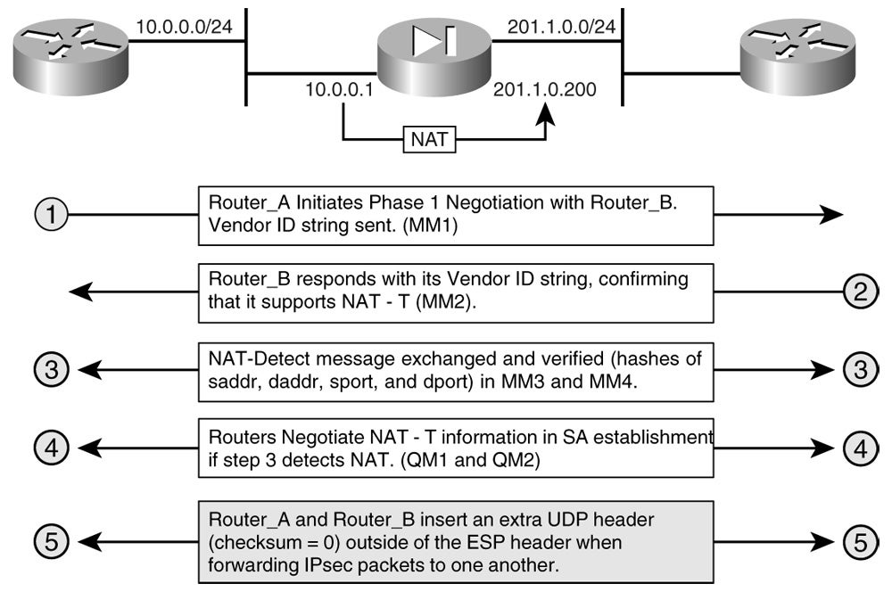
Consider the example described in Figure 4-10 in which two routers, Router_A and Router_B, communicate with one another through a firewall, Ent_FW.
Routers A and B are both capable of NAT-T, and dynamically agree on the handling of IPsec packets across the NAT’d path through the following sequence of exchanges:
Router_A sends its vendor ID to Router_B during IKE Phase 1 negotiation. This phase of NAT-T is commonly referred to as a “NAT Support” exchange.
Router_B sends its vendor ID string payload to Router_A during IKE Main Mode (MM1 and MM2, Phase 1) negotiation, letting Router_A know that it does indeed support NAT-T. This is also known as a “NAT Support” exchange in NAT-T context.
After Routers A and B have agreed on NAT-T Support, they must determine if NAT exists between the two of them. This phase is commonly referred to as “NAT Detect.” In this phase of NAT-T, multiple NAT-D payloads are exchanged between source and destination. NAT-D payload consists of an address and a hash. Each peer typically sends two NAT-D payloads to the other in main mode (MM3 and MM4)—one for the destination address followed by another for the source address. When NAT-D payloads are sent between each peer, the hashes are verified at the remote end. If the hash values match, then it can safely be determined that NAT doesnot exist. If the hash values do not match, then it can safely be determined that NAT does exist.
After NAT-D payloads are exchanged to detect NAT information, IPsec Quick Mode messages are exchanged to decide which peer (none, either, or both) will use NAT-T. This negotiation is performed during IKE Phase 2 in Quick Mode (QM1 and QM2).
In Figure 4-10, inside source address translation is being performed by the PIX. IPsec endpoints have determined this behavior using NAT-T steps 1-4 described above. In this case, Routers A and B will both encapsulate ESP packets in UDP, hereby remedying three incompatibilities with IPsec and NAT:
Incompatibility between ESP and AH with PAT
Incompatibility between IKE fixed ports and PAT
Incompatibility between UDP checksums and NAT (intermediate NAT-T UDP header checksum set to 0)
Note – As noted above, Cisco IOS will attempt NAT-T during IKE Phase 1 negotiation. Cisco IOS configures NAT-T automatically, and there is no manual configuration required. To disable the encapsulation of ESP packets in UDP using NAT-T, execute the following command from the IOS CLI:
IPsec SPIs provide another element that a NAT device can use to forward data between two endpoints. When IPsec traffic is passed through a NAT device, various crypto-protected elements are often translated by NAT, including source IP addresses, destination IP addresses, source ports, and destination ports. Another field that can be use to populate the translation table in a NAT device is the IPsec SPI. As we had discussed previously, though, IPsec and NAT incompatibilities arise when overlapping IPsec tunnels with overlapping SPIs are passed through the NAT device.
Cisco IOS releases 12.2T and later employ a predictive SPI selection algorithm on IPsec crypto endpoints that enable them to select unique SPIs during IKE. This effectively enables a NAT device in the crypto path to use IPsec SPIs to build its translation table without encountering the translation and forwarding issues caused by overlapping SPIs discussed earlier in this chapter.
Consider again the scenario in Figure 4-9, but with predictively selected SPIs and SPI matching enabled on the NAT device. The NAT device is now capable of differentiating between multiple initiators (sources) in its forwarding table without the use of PAT. Instead, SPI matching is used to differentiate between the two IPsec VPN tunnel initiators, Routers A and B.
The Influence of IPsec on Traffic Flows Requiring QoS
As networking technologies begin to mature and become more widespread, time- and delay-sensitive applications are increasingly migrating toward a converged solution. Many of these applications are considered critical to the needs of businesses in different vertical markets. As such, a need for guaranteed timely delivery and ordering of these applications emerges. In today’s networked environment, a variety of QoS mechanisms exist to guarantee the timely delivery of delay-sensitive business critical data communications in IP networks. QoS in and of itself is so broad and deep in scope that we cannot cover it in its entirety. We will, however, discuss several common inconsistencies between IPsec and QoS that present design challenges:
Traffic Flow Hash Ubiquification: Flow-based QoS techniques, such as Weighted-Fair queuing (WFQ) rely on the original source and destination IP addresses of the packet to hash traffic flows in to “conversations.” Certain IPsec protocols and modes effectively ubiquify the information needed to perform this hashing decision—the source and destination IP address. Consider the example of IPsec ESP in Tunnel mode. In this example, the inner IP header will be encapsulated within the ESP boundary and encrypted. Therefore, if the router wants to use WFQ to hash this traffic flow into a conversation, it will not be able to, as it will be unable to read the encrypted original source and destination IP address. Because most VPN endpoints supporting QoS rely on flow-based QoS techniques such as WFQ and Low-Latency Queueing/class-based weighted fair queueing (LLQ)/(CBWFQ), it is critical that the IPsec VPN endpoint have the capacity to classify traffic flows before IPsec or generic routing encapsulation (GRE) encapsulation or both. Cisco IOS offers this functionality with the IPsec Preclassify feature.
Packet Reordering and the IPsec Antireplay Window: If packets are received outside of the antireplay window in an IPsec VPN, they will be dropped. The nature of QoS is to reorder packets, which can sometimes result in delay of queued traffic. It is critical to ensure that n delays are not so long as to result in the packet being received outside of the antireplay window on the receiving VPN endpoint. Cisco IOS offers the capacity to extend the antireplay window on VPN endpoints to alleviate antireplay window errors if they should arise.
Packet Marking Obfuscation and (LLQ/CBWFQ): LLQ/CBWFQ is a QoS technique for reordering traffic flows locally on a network device. LLQ/CBWFQ requires that packets within a traffic flow be identified in some way. This is typically achieved by marking the packet by setting the DiffServ bits in the IP header. Network devices are therefore able to differentiate that traffic from other traffic flows and treat it (queue it) with the appropriate level of urgency. The scope of effect of LLQ/CBWFQ decisions is contained to the local device only.
Resource Reservation Protocol (RSVP): RSVP uses an exchange of RSVP signaling messages between two endpoints to reserve resources for delay-sensitive traffic between the two endpoints. Unlike LLQ/CBWFQ, where LLQ/CBWFQ classification and queuing decisions are local in scope, the scope of RSVP queueing decisions is end-to-end. Although RSVP can be configured to work in tandem with DiffServ-based QoS, it can also be configured to place traffic in the RSVP-reserved queue regardless of what type of DiffServ policy is configured on that specific network node.
Note – For more detailed information on LLQ/CBWFQ and DiffServ, visit CCO at the following URLs:DiffServ—The Scalable End-to-End QoS Model
As mentioned previously, QoS requires the use of end-to-end messaging techniques and the interpretation of certain bit values within the IP header. In some cases, if care is not taken during an IPsec/QoS deployment, IPsec can obfuscate the necessary messaging and IP header bits needed to deliver QoS. We will discuss QoS within this context, and explore some available techniques for delivering QoS within an IPsec VPN deployment.
IPsec’s Influence on DiffServ and LLQ/CBWFQ
In this section, we will explore a Voice over IP (VoIP) deployment in a branch networking scenario. VoIP is delay-sensitive—that is to say that packets must be received in order with consistent delay (low jitter). As shown in Figure 4-11, two routers want to communicate with each other over a series of wide-area links of varying bandwidths. On the lower-speed links, packets can sometimes be dropped due to oversubscription of the available bandwidth. Therefore QoS is required to ensure that the voice (RTP) packets are not dropped when this occurs (other packets are dropped instead). For these reasons, QoS must be used for IP traffic over the Frame-Relay links.
DiffServ is implemented in conjunction with LLQ/CBWFQ to deliver QoS for voice traffic to and from the branches. Because the company’s security policy mandates confidentiality for voice traffic, IPsec VPNs have been configured between the enterprise headend router and all branch routers, posing several design considerations with the IPsec/DiffServ requirements:
If AH is used, changes to the IP header are not permitted (the AH MIC invalidates them on the receiving VPN endpoint). This prevents remarking on network devices between the phones. Therefore, RTP traffic must be marked accordingly prior to IPsec encapsulation (either on the routers or phones) if AH is used.
In both AH and ESP, if packets are received outside the antireplay window, they are dropped. Therefore, if traffic is delayed in queue due to QoS decisions, it could get dropped if it is received outside of the antireplay window at the opposite end of the IPsec VPN tunnel.
With ESP, the original IP header and QoS information is encapsulated in ESP and encrypted with the appropriate transform. This effectively renders the DiffServ bits needed for QoS unreadable by intermediate network nodes between the two IPsec VPN endpoints. Unless these bits are successfully copied to the outer IP header ESP encapsulation, network nodes between the two IPsec VPN endpoints may not appropriately classify the IPsec-processed RTP packet.
IPsec’s Effect on IntServ and RSVP
In addition to issues outlined with the DiffServ and LLQ/CBWFQ, RSVP implementations with IPsec VPNs provide further design issues to address. As we had mentioned previously, RSVP provides a signaling method to proactively provision resources between a given source and destination. RSVP does so by exchanging a series of RSVP PATH and RSVP RESV messages between the source and destination. If intermediate network nodes between the RSVP source and destination are unable to decipher the RSVP RESV messages, as would be the case if they were encrypted in an IPsec VPN, intermediate network nodes cannot use the RSVP-RESV messages to dynamically reserve resources between source and destination (illustrated in Figure 4-12).
Therefore, to dynamically provision resources on intermediate nodes between a source and destination that require timely, ordered delivery of IP-based application traffic, RSVP signaling messages must be forwarded outside of the crypto path.
Solving Fragmentation Issues in IPsec VPNs
In IPsec VPN environments, it is critical to address MTU and fragmentation issues. Otherwise, the entire VPN is at risk of performance and operation issues. We will discuss the effect of fragmentation reassembly and MTU issues in this section, and provide solutions for proper IPsec design in environments in which MTU is likely to be exceeded, resulting in fragmentation.
The effect of fragment handling between encryption devices is largely focused on the encryption device that is performing the reassembly of the fragmented packet. Although most network devices and VPN endpoints available today can fragment encrypted packets in the crypto-switched fast path, the decrypting IPsec endpoint must decrypt all fragments in the chain before the packet can be reassembled. Figure 4-13 illustrates an IPsec VPN deployment in which packets are reassembled prior to decryption on the destination IPsec VPN gateway.
This reassembly behavior is done at the process level and greatly affects the performance of the VPN. In IPsec environments, every precaution should be taken to fragment packets before they are encrypted with IPsec so that administrators can be assured that both fragmentation and reassembly is being done on devices with the appropriate computational resources available.
Path MTU Discovery
IP PMTUD is a technology that is used to dynamically discover the maximum MTU size between two endpoints such that the originating device fragments packets to the lowest MTU of the path. As such, PMTUD prevents intermediate network devices from fragmenting packets and causing excessive CPU overhead on the receiving IPsec endpoint doing the reassembly. Consider the scenario described in Figure 4-14, in which Host_A wishes to open a TCP session to Server_B across a routed IP network using Routers A, B, and C.
Administrators have enabled IP PMTUD on their workstations and servers such that fragmentation reassembly issues can be avoided on Router_B. Host_A executes PMTUD using the following process:
Host_A creates an IP packet sized to the appropriate MTU of its locally attached segment and sets the DF bit before transmitting it to Server_B.
Router_A receives the packet, notes that the DF bit is set. Router_A’s serial link has an MTU of 1414. Because the DF bit is set and the packet from Host_A to Server_B exceeds the MTU of the serial interface, it is dropped.
Router_A sends an ICMP Unreachable message back to Host_A, carrying the MTU (1414) of the next hop (the serial interface between Router_A and C).
Host_A sends another ICMP message of 1414 bytes in length to Server_B with the DF bit set.
Router_A receives the packet and forwards to Router_C. Router_C receives the packet, and notes that the DF bit is set. Because the DF bit is set and the packet is greater than the MTU of Router_C’s link to Router_B (512), the packet is dropped.
Router_C sends an ICMP Unreachable message back to Host_A, carrying the MTU (512) of the next hop (serial interface between Router_C and A).
Host_A sends another ICMP message of 512 bytes in length to Server_B with the DF bit set.
The 512 byte ICMP message is lower than the MTU of any individual link in the path. It is therefore successfully forwarded to Server_B. Server_B sends an ICMP Echo Response back to Host_A, indicating to Host_A that 512 is the MTU of the path.
Note – The routers in the above scenario are used to illustrate the general operation of PMTUD. IPsec and IPsec+GRE tunnels use a slightly different configuration of PMTUD than the previous, known as “Tunnel Path MTU Discovery.” The specific operation of fragment handling using PMTUD in IPsec and IPsec+GRE environments is discussed in greater detail later in this chapter.
IPsec in Cisco IOS can be configured to copy the DF bit value in to the outer IP header in ESP-processed packets. As such, the ICMP traffic that PMTUD relies on to operate correctly does not have to be explicitly excluded from the crypto switching path.
There are several issues that must be addressed if PMTUD is to be part of one’s design strategy to mitigate fragmentation reassembly issues in IPsec VPNs. In this section, we will briefly highlight some of the most common ones:
Permitting ICMP Unreachable Messages
Rate-Limiting ICMP Messages
PMTUD Not Supported on End-Hosts
Adjusting TCP Maximum Segment Size
Clearing the DF-Bit
Permitting ICMP Unreachable Messages
As we’ve discussed previously in our overview of the PMTUD protocol, PMTUD relies heavily on ICMP unreachable messages to communicate the MTU of segments back to the fragmenting host. It is very common for security devices, such as firewalls, to deny ICMP unreachable messages, as they are commonly used in malicious scanning techniques by hackers. As such, care must be taken to ensure that all paths between PMTUD-enabled endpoint be checked to ensure that ICMP unreachables are indeed allowed to pass if PMTUD is to be the preferred message for fragmentation avoidance along the path.
Rate-Limiting ICMP Messages
Because PMTUD relies on the receipt of ICMP Unreachable replies within a given retransmission window on the originating host, care should be given to rate-limiting techniques applied to ICMP messages, as they could cause premature retransmission of ICMP messages in PMTUD environments. If received out of order, ICMP unreachable messages in a PMTUD environment could cause confusion on MTU settings for the originating PMTUD host. For example, ICMP Unreachable messages delayed in rate-limiting queues could signal an erroneous MTU setting on the originating PMTUD host if that Unreachable message is received after a valid ICMP Unreachable with the correct IP MTU.
PMTUD Not Supported on End-Hosts
If PMTUD is disabled on the hosts within a network, it is recommended that the network administrator take steps to ensure that packets are fragmented in the network at some other location before crypto processing occurs. This can be achieved through enabling IPsec Lookahead Fragmentation in Cisco IOS and setting the DF bit in IPsec-processed packets. With IPsec Lookahead Fragmentation, the IOS IPsec VPN endpoint will attempt to determine the encapsulated packet size before it is encrypted. If the encapsulated packet size is predetermined to be larger than the path MTU, it is fragmented before encryption. When the DF bit is set, the encrypting router will look for information in any ICMP unreachable message received for updates it needs to install to the Path MTU entry in its SADB. Alternately, if the VPN endpoint does not support functionality similar to IPsec Lookahead Fragmentation or explicit setting of the DF bit in outer IP headers, the MTU of the IPsec VPN tunnel can be manually defined to avoid fragmentation reassembly issues.
Adjusting TCP Maximum Segment Size
Hosts sending IP packets greater than the TCP Maximum Segment Size (MSS) are at risk of fragmentation. Strictly speaking, the TCP MSS is the maximum amount of data that a host is willing to accept in an IP datagram. Hosts compare TCP MSS buffers sizes with MTU to determine the MTU for their transmissions. The result will be the lower of the TCP MSS or the MTU less 40 bits (an allocation for IP header and TCP header, both 20 bits in length). Once determined, each host communicates the selected values to the opposite host via the following exchange described in Figure 4-15.
The following order of events describes the sequence illustrated in Figure 4-15 above:
Host_A has an MSS buffer of 20k and an MTU of 1500. It compares the MSS buffer with the MTU of the link, less a 40-bit allocation for IP and TCP header addition (1500 – 40 = 1460) and selects the lower value of 1460 (1460 < 20000) to send to Host_B.
Host_B has a 16k MSS buffer and a 2048 interface MTU size. It does a similar comparison to Host_A’s in step 1 and selects 2008 (2048 – 40). It then compares the received value from Host_A and selects the lower value of 1460 as its MSS value (1460 < 2008).
Host_B signals its MSS of 2008 to Host_A.
Host_A compares the received value of 2008 with its TCP MSS value derived in Step 1 and selects the lower of the two values, 1460, as its TCP MSS.
TCP MSS values use MTU values to help avoid fragmentation. In the example above, MTU values are selected, as they are smaller than TCP MSS values. However, if the MSS value were to be smaller than the MTU, then Hosts A and B will select the MSS + 40 bytes as the maximum packet length for TCP traffic. Note that, in this case, the larger MTU value would still be used for UDP traffic.
Clearing the DF-Bit
If the DF bit is cleared somewhere along the PMTUD path between source and destination, the network nodes along the path will fragment the ICMP PMTUD message rather than dropping it and replying with an ICMP unreachable. This will obviously break the operation of PMTUD. Most IP-enabled devices available today are capable of clearing the DF bit in an IP header.
Fragmentation Behavior on Cisco IOS VPN Endpoints
The overhead associated with IPsec and IPsec+GRE encapsulated IP packets can often lead to fragmentation, which is why PMTUD is, by default, enabled on IPsec VPN routers. However, the specifics of fragment handling and PMTUD differ slightly from nonVPN environments. In this section, we will discuss the handling of fragments in IPsec and IPsec+GRE tunnels and some additional solutions available for avoiding fragmentation in IPsec VPN environments.
IPsec VPNs use Tunnel Path MTU Discovery to interpret MTU information of ICMP Unreachable messages and update the Path MTU of the corresponding IPsec SA. The typical PMTUD operation and fragment handling of an IPsec VPN is illustrated in Figure 4-16.
Fragment Handling and PMTUD Operation with IPsec Tunnels
The following describes the operation illustrated in Figure 4-16:
Host_A sends a 1500-byte (size of the local interface MTU) packet to Server_B.
Router_A receives the packet sent in 1 above, and observes that the ESP encapsulated packet size exceeds the MTU of the serial link to B. Because Host_A set the DF bit of the packet, Router_A drops the packet and sends an ICMP unreachable message containing the MTU size of 1442 (1500bytes—58bytes max ESP overhead) back to Host_A.
Host_A receives the ICMP Unreachable message with the MTU information, and forwards another ICMP packet of 1442 bytes in length to Router_A. Router_A encapsulates the packet with ESP and forwards it across the VPN with the DF bit set in the outer header.
Router_C receives the ICMP message from Router_A in Step 3 and notes that the packet exceeds the MTU of its serial interface to Router_B. Because the DF bit is set, Router_C drops the packet and forwards an ICMP Unreachable to Router_A with the MTU size of 1440 embedded.
Router_A receives the ICMP Unreachable message from Router_C in Step 4. Router_A notes the MTU size of 1440 in the PMTU field of the SA that is established with Router_B. Router_A does not send a new ICMP message of 1440 in length, but instead this is handled by Host_A in step 6.
Host_A retransmits an ICMP message of 1442 in length, as it never received an acknowledgement from the original ICMP message sent in Step 2.
Router_A compares the ESP-encapsulated packet size (1442+58) of the packet received in step 6 above with its path MTU (1440) and drops the packet. Router_A responds with an ICMP unreachable with the MTU of 1342 (1400 PMTU less ESP overhead of 58 bytes) embedded.
Host_A sets its MTU to 1342 and forwards a new 1342-byte message to Server_B. The message and associated ESP overhead is now lower than the end-to-end path MTU, resulting in a successful transmission from Host_A to Server_B.
As we’ve discussed in previous sections of this chapter, and in others, it is sometimes necessary to encapsulate certain traffic types in GRE prior to processing them with IPsec. Processing of multicast traffic, for example, is one instance in which one would seek to encapsulate the plain text traffic in GRE prior to encapsulating it in ESP. This is commonly referred to as IPsec+GRE. This process includes an additional 24 bytes of overhead, as the GRE header is applied in addition to the ESP or AH headers. More importantly, it adds additional steps to the Tunnel PMTUD operation while trying to avoid fragmentation. Figure 4-17 illustrates the fragment handling process using PMTUD in an IPsec+GRE scenario.
Fragment Handling and PMTUD Operation with IPsec+GRE Tunnels
The operation of PMTUD over an IPsec+GRE tunnel illustrated in Figure 4-17 is described by the following order of events:
Host_A sends a 1500byte packet with the DF bit set to Server_B.
Router_A receives the packet and observes that the DF bit is set. GRE encapsulation occurs prior to ESP encapsulation in this scenario, so the GRE process on the router drops the packet as the 1500byte packet + 24bytes of GRE overhead exceeds the GRE tunnel MTU of 1500. Router_A sends an ICMP Unreachable back to Host_A with an embedded MTU value of 1476 (1500—GRE header length of 24).
Host_A sends a 1476 byte packet with the DF bit set to Server_B.
Router_A receives the packet, noting that the DF bit has been set. The router encapsulates the packet in GRE and then attempts to encapsulate it in ESP. The added ESP encapsulation pushes the MTU over the serial interface MTU of 1414, so Router_A drops the packet. ESP sends an ICMP error message to GRE indicating an MTU of 1376 bytes (1414 less max ESP header length of 38 bytes). GRE records this value as the new tunnel IP MTU.
Host_A retransmits the 1476-byte packet in step 3, as no acknowledgement was received. Router_A drops this packet as it exceeds the tunnel IP MTU derived in step 4. Router_A responds with an ICMP Unreachable message with the tunnel IP MTU of 1414.
Host_A sends a new ICMP message of 1414-bytes in length to Server_B. Router_A encapsulates in GRE, and then encapsulates in ESP. The DF bit is copied to the outer IP header in the ESP packet before transmitting across the IPsec VPN.
Router_C receives the packet, and notes that the DF bit is set. The size of the packet is now 1414, as GRE and ESP headers have been added to the original ICMP message sent in step 6. Router_C drops the packet, as it exceeds the MTU of the link to Router_B and has the DF bit set. Router_C sends an ICMP unreachable message to Router_A with the MTU of 1400.
Router_A receives the ICMP unreachable message from Router_C in step 7 above and updates the PMTU field of its IPsec SA to Router_B with the 1400-byte value.
Host_A retransmits the 1414-byte ICMP message in step 6 to Server_B, as no acknowledgement was received.
Router_A receives the packet, and encapsulates it in GRE. Once ESP encapsulation is applied, the length of the packet exceeds the 1400-byte IPsec SA PMTU obtained from Router_C in step 8. ESP sends an ICMP message to GRE with an MTU of 1342 (1400—58 bytes max ESP header length). GRE updates its tunnel IP MTU with this value.
Host_A retransmits the 1414-byte ICMP message in step 6 again, as no acknowledgement was received from the retransmission in step 10.
Router_A receives the packet and drops it as it exceeds the new GRE tunnel IP MTU of 1342 and has the DF-bit set. Router_A forwards an ICMP Unreachable to Host_A with an MTU value of 1318 bytes (1342 GRE MTU less 24 bytes GRE overhead).
Host_A receives the ICMP Unreachable message sent from Router_A in step 12, and sends a new 1318-byte ICMP message to Server_B with the DF bit set.
Router_A receives the packet, encapsulates it in GRE, encapsulates it in ESP, sets the DF bit in the outer IP header, and forwards to Router_C. This time, Router_C forwards the ICMP message originated from Host_A to Router_B.
Router_B decapsulates the ESP packet, then decapsulates the GRE packet, and finally forwards the original ICMP PMTUD message to Server_B.
Server_B acknowledges the receipt of the message, confirming that Host_A is to use an MTU size of 1338 bytes for this path.
Although the DF bit in PMTUD ICMP messages is always set so as to properly detect areas of fragmentation, ICMP Unreachable responses to these messages are sent with the DF bit set to 0. As such, it is important to note that ICMP PMTUD messages sent from source to destination will never be fragmented, but the responses to those messages could quite possibly be fragmented along the return path.
Solutions for Preventing Fragmentation
In previous sections, we’ve discussed the most common method for preventing fragmentation—Path MTU Discovery. However, as we have explored, the use of PMTUD is somewhat laborious for network devices to execute. Additionally, PMTUD may not be an option in networks that require the filtering of ICMP messages at various points within the network. As such, it is important to understand other ways in which fragmentation can be avoided when designing an IPsec VPN. We will discuss several techniques for mitigating IP fragmentation other than PMTUD in this section.
IPsec Prefragmentation
IPsec Prefragmentation is a Cisco IOS feature that enables an encrypting IPsec VPN endpoint to attempt fragmentation before encryption if a size of the encrypted packet and additional header information exceeds the MTU of the path in between endpoints. PMTUD can be used to determine the path of the SA and the MTU of that path. Doing so in conjunction with IPsec Prefragmentation provides a very scalable and manageable method of increasing the overall performance of an IPsec VPN where fragmentation after encryption is a possibility. Example 4-34 illustrates how to configure IPsec crypto DF-bit overwrite with IPsec Lookahead Fragmentation such that the path MTU of the SADB will be dynamically determined using tunnel PMTUD, and large packets will be fragmented (those exceeding the Path MTU for that SA in the SADB) before encryption.
Example 4-34 Enabling IPsec Prefragmentation with PMTUD and Crypto DF-bit Rewrite
Router_A#config
Router_A#configure terminal
Enter configuration commands, one per line. End with CNTL/Z.
Router_A(config)#crypto IPsec df-bit set
Router_A(config)#crypto IPsec fragmentation before-encryption
Router_A(config)#
Note – Although in the case of Example 4-34, Router_A will attempt to fragment large packets before encrypting them, there are many configuration instances in which IPsec Lookahead Fragmentation and DF-bit overwrite are configured incorrectly. It is critical to understand the interdependencies of the DF-bit setting and the Lookahead Fragmentation setting addressing IPsec fragmentation design considerations. For a full listing of DF-bit interoperability with IPsec Lookahead Fragmentation settings, please refer to the following URL on CCO:
Figure 4-18 illustrates a client server exchange that does not support PMTUD. Note that, even though there is no exchange of ICMP messages, the Path MTU is still discovered and updated in Router_A’s IPsec SADB.
There are three key operations that enable this feature:
Lookahead Fragmentation: Before forwarding an IPsec packet, Router_A predetermines the encapsulated packet size, and compares it with the MTU in the SADB. If it is predetermined to exceed that MTU size, the packet is fragmented before it is encrypted.
Crypto DF-bit Rewrite: When PMTUD is not supported, it is important that Router_A be able to set the DF bit in the outer IP header of IPsec-encapsulated packets. This prevents fragmentation, and triggers ICMP unreachables needed to adjust the Path MTU in Router_Aís SADB.
Processing of MTU Information in ICMP Unreachables: Router_A is capable of deciphering MTU information of ICMP unreachables (received when IPsec packets with DF=1 are dropped). It uses this information to dynamically update the path MTU in its SADB.
The exchange between Router_A and Router_B in Figure 4-18 illustrates how all of these three features work in concert to minimize the effect of postencryption fragmentation in IPsec VPN deployments where PMTUD is note-enabled on the endstations:
IPsec Fragment Handling Without PMTUD-Enabled Endstations
Host_A sends a 1500-byte data packet, destined for Server_B.
Router_A receives the packet, and estimates the ESP encapsulated packet size before encrypting or forwarding the packet. Router_A compares the estimated encapsulated packet size with the Path MTU, and determines that the size is greater than the Path MTU and fragments the packet.
Router_A applies the appropriate encapsulation to the fragments in the fragment chain. While doing so, it sets the DF bit of each encapsulated packet equal to 1.
Router_C receives the packets from Router_A, compares them with the MTU of the Router_C to Router_B link, notes that DF=1, and drops larger packets accordingly. Router_C sends ICMP Unreachables for dropped packets to Router_A.
Router_A receives the ICMP Unreachables from Router_C, and updates the MTU of its SADB accordingly.
Host_A does not receive a reply to its original packet within the appropriate timeout window and therefore retransmits.
Router_A performs Lookahead Fragmentation on the retransmitted packet, sizing the fragments to the new MTU in its SADB. It then sets the DF bit in each encrypted packet.
The encrypted packets are now sized lower than any individual link MTU in the path (<1400 bytes), and are therefore received on Router_B. Router_B is now able to decrypt each fragment in the chain before they are reassembled, a process that is done in the fast switching path.
Manual MTU Adjustment
We’ve discussed the many tools available within Cisco IOS to avoid fragmentation in IPsec VPNs without having to manually tune the MTU sizes within the network. However, the option still exists to increase MTU size between IPsec VPN endpoints such that the risk of receiving a packet smaller than that MTU size is small. If one must tune MTU sizes to accommodate IPsec traffic between endpoints in a network, one should take the following disadvantages to this approach into consideration:
Scalability and Management: Remember that MTU sizes vary on a segment-by-segment basis. As such, it can become laborious for network administrators to consistently ensure that every segment’s MTU is properly tuned. Network designers can anticipate the difficulty of manual MTU tuning to increase as the number of IPsec VPN connections and hosts scales upwards.
Serialization Delay: The MTU attribute exists to decrease serialization delay on networks. On segments that have artificially high MTU sizes, network administrators can expect increased delay as larger packets are serialized in queue. This adversely affects time- and delay-sensitive applications such as Voice and Video over IP.
Note – For more information on serialization delay and other common troubleshooting and design issues with VoIP, please refer to the following link on CCO:
Recursive routing commonly occurs when a router attempts to install a route over the same route that it is using to learn that route through a given RP. Because multicast updates inherent to most RP operations are unable to be crypto-switched, the effect of recursive routing is most commonly seen in the IPsec+GRE solution in which GRE is used to encapsulate RP traffic prior to IPsec (ESP or AH) encapsulation. We will explore a recursive routing situation in an IPsec+GRE scenario outlined in Figure 4-19.
The following order of events describes the influence of the recursive routing scenario in the IPsec+GRE deployment illustrated in Figure 4-19:
Router_A and Router_B look up the GRE tunnel destination interfaces in their routing tables in order to build the GRE tunnel. They both find routes installed in their routing table for the appropriate tunnel destination interfaces and build the GRE tunnel accordingly using the statically configured default route (Example 4-35, line 30).
Router_A and Router_B are configured to encrypt all GRE traffic between each other using ESP. Therefore, all exchanges across the GRE tunnel will be kept confidential.
Router_A and Router_B inject all directly connected routes in to their routing protocol, Enhanced Interior Gateway Routing Protocol (EIGRP) AS1 (Example 4-35, line 24). This includes the loopback192 interfaces and the GRE tunnel interfaces.
Router_A and Router_B build an EIGRP adjacency across the GRE tunnel and begin to exchange routing updates with one another.
Router_A and Router_B learn the static routes installed in step 1 recursively across the GRE tunnel via EIGRP 1, and attempt to install the routes in the routing table. EIGRP learns a more specific route to the GRE tunnel destination than the default used in step 1 above.
Once Router_A and Router_B are instructed to learn each other’s tunnel destinations of the GRE tunnel interface (rather than via the static default routes in step 1), they determine that the behavior is recursive, and clear the route from the routing table. This causes both the GRE tunnel and the EIGRP adjacency to go down.
When a recursive routing situation occurs in an IPsec+GRE scenario, IOS CLI will write messages to the console, indicating the failure. Other symptoms indicative of recursive routing failure include RP adjacency loss across the GRE tunnel, which are also written to the IOS CLI. Example 4-35 shows recursive routing configuration errors described in Figure 4-19 and steps 1-6 above. Symptoms of recursive routing in IPsec+GRE scenarios are shown in Example 4-36.
Example 4-35 Configuration Errors Leading to Recursive Routing (Topology in Figure 4-19)
Example 4-36 provides the diagnostic output on Router_A that confirms that the GRE tunnel and EIGRP adjacency failures are due to the recursive routing behavior described above. Lines 10 and 18 show the presence of the static route that was used to build the GRE tunnel prior to occurrence of recursive routing. However, line 18 of Example 4-36 shows that there is a recursively learned EIGRP route to the tunnel destination (192.168.2.1) over the tunnel interface itself (next hop of 192.168.0.2). Because this route is more specific than the default route, EIGRP installs it in the routing table, causing the tunnel to fail due to recursive routing (as confirmed in Example 4-36, lines 20 and 21). Once the tunnel fails, EIGRP tears down the adjacency, as illustrated in Example 4-36, line 22.
Example 4-36 Recursive Routing Symptoms and Diagnostic Output in Cisco IOS
1  Router_A#show ip route
2  Codes: C - connected, S - static, R - RIP, M - mobile, B - BGP
3     D - EIGRP, EX - EIGRP external, O - OSPF, IA - OSPF inter area
4     N1 - OSPF NSSA external type 1, N2 - OSPF NSSA external type 2
5     E1 - OSPF external type 1, E2 - OSPF external type 2
6     i - IS-IS, su - IS-IS summary, L1 - IS-IS level-1, L2 - IS-IS level-2
7     ia - IS-IS inter area, * - candidate default, U - per-user static route
8     o - ODR, P - periodic downloaded static route
9
10 Gateway of last resort is 200.0.0.2 to network 0.0.0.0
11
12    200.0.0.0/30 is subnetted, 1 subnets
13 C    200.0.0.0 is directly connected, Ethernet0/0
14    192.168.0.0/30 is subnetted, 1 subnets
15 C    192.168.0.0 is directly connected, Tunnel192
16    192.168.1.0/32 is subnetted, 2 subnets
17 C    192.168.1.1 is directly connected, Loopback192
18 D    192.168.2.1 [90/297372416] via 192.168.0.2, 00:00:04, Tunnel192
18 S*  0.0.0.0/0 [1/0] via 200.0.0.2
19 Router_A#
20 *May 8 15:42:10.439: %TUN-5-RECURDOWN: Tunnel192 temporarily disabled due to recursive routing
21 *May 8 15:42:11.439: %LINEPROTO-5-UPDOWN: Line protocol on Interface Tunnel192, changed state to down
22 *May 8 15:42:11.447: %DUAL-5-NBRCHANGE: IP-EIGRP(0) 100: Neighbor 192.168.0.2 (Tunnel192) is down: interface down
In order to prevent this behavior, the administrators of Router_A ensure that the route to the GRE tunnel destination is not learned over the GRE tunnel itself. This can be accomplished by excluding the routes used to establish the GRE tunnel from being redistributed in to EIGRP using either a route-map or distribute list. Example 4-37 provides an example of how to accomplish this using an EIGRP route-map.
Example 4-37 Controlling EIGRP Route Redistribution with Route-Maps and ACLs
access-list 1 deny  192.168.1.0
!
route-map no-recursive permit 10
 match ip address 1
Example 4-38 provides an alternative to excluding routes from the EIGRP redistribution using a distribute list. In the context of this particular example, the configuration in Example 4-38 will accomplish the same task as the route-map configuration in Example 4-37.
Example 4-38 Controlling EIGRP Route Redistribution with Distribute Lists
router eigrp 1
 redistribute connected
 network 192.168.0.0
 default-metric 1500 100 128 128 4700
 distribute-list 1 in
 no auto-summary
!
access-list 1 deny  192.168.1.0
access-list 1 permit any
Example 4-39 shows an example of EIGRP and GRE tunnel reestablishment once the appropriate route-map and ACL combination have been applied to the EIGRP routing protocol process using the redistribute connected route-map [route-map-name] command.
Example 4-39 GRE Tunnel and EIGRP Adjacency Reestablishment when Excluding Redistribution of Recursively-Learned Routes Using Route-Maps and ACLs
router eigrp 1redistribute connectednetwork 192.168.0.0default-metric 1500 100 128 128 4700no auto-summary!
crvpn-3600-a#conf t
Enter configuration commands, one per line. End with CNTL/Z.
crvpn-3600-a(config)#router eigrp 1
crvpn-3600-a(config-router)#redistribute connected route-map no-recursive
*May 8 16:27:44.191: %DUAL-5-NBRCHANGE: IP-EIGRP(0) 1: Neighbor 192.168.0.2 (Tunnel192) is up: new adjacency
Summary
In this chapter, we’ve covered several different broader areas of common issues with IPsec VPN deployments. The first area of common IPsec VPN issues we discussed pertains to configuration of ISAKMP and IPsec themselves, including
IKE SA Proposal Mismatches
IKE Authentication Errors
IPsec SA Proposal Mismatches
Crypto ACL Mismatches
When IKE is used, an IKE Phase 1 SA must be established before any additional IPsec SA negotiation can occur. The first task that crypto endpoints must accomplish to build an IKE SA is agreement on IKE SA proposals. We’ve discussed IKE SA proposal mismatches in the context of each of the following attributes that must be agreed on for a successful IKE SA proposal match:
IKE Authentication Method (PSKs, RSA Encryption, or RSA Signatures)
IKE Encryption Cipher (DES, 3DES, AES)
IKE Hash Algorithm (MD5, SHA1)
Diffie-Hellman Group Modulous (1, 2, or 5)
IKE SA Lifetime (60-86400 seconds)
Once IKE SA proposals have been agreed upon, the IKE SA must be authenticated. In this chapter, we’ve explored common techniques for IKE SA proposal troubleshooting and IKE SA authentication troubleshooting with each of the three IKE SA authentication methods—IKE PSKs, RSA Encryption, and RSA Signatures. The methods presented in this chapter can be used to diagnose problems with IKE SA establishment and authentication and verify the existence of an IKE SA before proceeding to investigate potential issues with IPsec SA establishment.
Unless IPsec SAs are manually defined, an IKE SA must exist on the crypto endpoints before an IPsec SA can be established. Once an IKE SA has been confirmed to exist, measures should be taken to confirm that the two crypto endpoints have agreed on IPsec SA proposals. In this chapter, we’ve discussed techniques IPsec SA failures attributable to mismatches in each of the following attributes:
The IP addresses used for IPsec tunnel termination
The symmetric IPsec transforms to use on crypto-protected traffic after an IPsec SA has been negotiated
The scope of protected traffic in the crypto switching path
When each of the previous attributes match, an IPsec SA can be formed. Techniques for verifying IPsec SA establishment were provided above to confirm the existence of an IPsec SA and the details of IPsec SA proposal agreed upon by the two crypto endpoints.
In addition to discussion of thorough discussion of configuration issues with IPsec VPN deployments, we have also introduced and discussed various architectural issues with IPsec VPN deployments. Unlike configuration issues, architectural issues pertain to incompatibilities and common design challenges when integrating IPsec with different technologies commonly found in the larger system architecture. Architectural issues discussed in this chapter include:
IPsec in Firewalled Environments
IPsec in NAT Environments
IPsec and QoS Inconsistencies
IPsec and Fragmentation
IPsec+GRE and Recursive Routing
When deploying IPsec through a firewall, several intrinsic design challenges surface. First, the appropriate protocols need to be allowed to pass for the IPsec and ISAKMP traffic to pass through the firewall. Recall that, for an IKE SA to establish successfully, UDP 500 must be allowed through. Once an IPsec tunnel has been built over IKE, the appropriate IP protocol number must be allowed (IP Protocol 50 for ESP and IP Protocol 51 for AH) for encrypted traffic to pass through the firewall. In our discussion of IPsec, we have also discussed the effect of fragmentation and the critical role that IP Unreachables play in PMTUD when preventing IPsec fragmentation after encryption. Firewalls typically do not send IP Unreachables. Therefore, when IPsec is deployed in conjunction with firewalls, it is important to ensure that MTUs are appropriately sized for the IPsec tunnel via some method other than PMTUD.
One primary strength of IPsec as a VPN technology is assurance that data is not manipulated while in transit between two crypto endpoints. When a NAT device is introduced between two crypto endpoints, often parts of the packets in transit are manipulated—specifically the source IP address, destination IP address, source ports, and destination ports. This behavior causes many intrinsic incompatibilities between NAT and IPsec, including:
IPsec AH Keyed MIC Failures in NAT Environments
Inbound IPsec SA Selector Inconsistencies in NAT Environments
IPsec Security Parameter Index Conflicts on NAT Devices
Embedded IP Address Translation Limitations
Unidirectional NAT Support
TCP and UDP Checksum Failures
IPsec introduces design challenges when deployed in conjunction with QoS. In this chapter, we’ve discussed how IPsec makes source and destination hash information opaque to intermediate notes that require that hash information to make Weighted-Fair Queueing decisions. We’ve also discussed how IPsec ubiquifies RSVP signaling information needed by intermediate notes to guarantee end-to-end QoS between to IP endpoints. IPsec incorporates protection against rollback attacks through incorporating an antireplay window. When QoS delays the transmission of encrypted packets outside of the antireplay window on the receiving host, the packet is dropped.
It is important to ensure that fragmentation in IPsec networks is facilitated before encryption takes place. This is because, when a decrypting IPsec endpoint receives a fragment chain, all of the fragments in the chain must be decrypted before the packet can be reassembled, an operation that is performed in the process-switched path. This behavior causes substantial performance and scalability considerations in IPsec VPN endpoints. Proper fragmentation is therefore a paramount design consideration to validate in an IPsec VPN deployment. In this chapter, we have provided several methods for ensuring that fragmentation in IPsec VPN deployments is executed properly, before encryption with IPsec.
The last architectural issue we have discussed in this chapter pertains to recursive routing in IPsec+GRE environments. Recall from our previous discussions that IPsec+GRE is a popular design choice, as it accommodates multicast traffic in the crypto switching path. Care must be taken when building GRE deployments that routes used to build the GRE tunnel are not then learned recursively over the GRE tunnel itself, resulting in the teardown of the GRE tunnel and the corresponding routing protocol adjacency formed over that tunnel.
In the following chapters, we will discuss resilient and highly available IPsec designs that build upon sound IPsec fundamentals introduced in this chapter and in previous chapters. When exploring each of the designs presented in subsequent chapters, it is important to consider each in the context of the common issues with IPsec VPN deployments presented in this chapter.