Cisco Press

Features of IPv6
IPv6 is a powerful enhancement to IPv4 with features that better suit current and foreseeable network demands, including the following:
Larger address space—IPv6 addresses are 128 bits, compared to IPv4’s 32 bits. This larger address space provides several benefits, including: improved global reachability and flexibility; the ability to aggregate prefixes that are announced in routing tables; easier multihoming to several Internet service providers (ISPs); autoconfiguration that includes link-layer addresses in the IPv6 addresses for “plug and play” functionality and end-to-end communication without network address translation (NAT); and simplified mechanisms for address renumbering and modification.
Simplified header—A simpler header provides several advantages over IPv4, including: better routing efficiency for performance and forwarding-rate scalability; no requirement for processing checksums; simpler and more efficient extension header mechanisms; and flow labels for per-flow processing with no need to examine the transport layer information to identify the various traffic flows.
Support for mobility and security—Mobility and security help ensure compliance with mobile IP and IP security (IPsec) standards.
Mobility enables people to move around in networks with mobile network devices, with many having wireless connectivity. Mobile IP is an Internet Engineering Task Force (IETF) standard available for both IPv4 and IPv6 that enables mobile devices to move without breaks in established network connections. Because IPv4 does not automatically provide this kind of mobility, supporting it requires additional configurations.
In IPv6, mobility is built in, which means that any IPv6 node can use it when necessary. The routing headers of IPv6 make mobile IPv6 much more efficient for end nodes than mobile IPv4 does.
IPsec is the IETF standard for IP network security, available for both IPv4 and IPv6. Although the functions are essentially identical in both environments, IPSec is mandatory in IPv6. IPSec is enabled and is available for use on every IPv6 node, making the IPv6 Internet more secure. IPSec also requires keys for each device, which implies global key deployment and distribution.
Transition richness—There are a variety of ways to transition IPv4 to IPv6.
One approach is to have a dual stack with both IPv4 and IPv6 configured on the interface of a network device.
Another technique uses an IPv4 tunnel to carry IPv6 traffic. One implementation is IPv6-to-IPv4 (6-to-4) tunneling. This newer method (defined in RFC 3056, Connection of IPv6 Domains via IPv4 Clouds) replaces an older technique of IPv4-compatible tunneling (first defined in RFC 2893, Transition Mechanisms for IPv6 Hosts and Routers, which has been made obsolete by RFC 4213, Basic Transition Mechanisms for IPv6 Hosts and Routers).
Cisco IOS Software Version 12.3(2)T (and later) also allows NAT protocol translation (NAT-PT) between IPv6 and IPv4, providing direct communication between hosts that are using the different protocol suites.
IPv6 Address Space
| Key Point | IPv6 Addresses Are 128 bits |
|---|---|
| IPv6 increases the number of address bits by a factor of 4, from 32 to 128, providing a very large number of addressable nodes. |
The increased number of address bits are illustrated in Figure 10-1. However, as in any addressing scheme, not all the addresses are used or available.
Figure 10-1
IPv6 Provides Four Times as Many Address Bits as IPv4
With 32 bits, IPv4 allows for approximately 4,200,000,000 possible addressable nodes, with some 2 billion usable addresses. Current IPv4 address use is extended by applying techniques such as private-to-public address space NAT and temporary address allocations (such as addresses leased by the Dynamic Host Control Protocol [DHCP]). However, the manipulation of the packet by intermediate devices complicates the advantages of peer-to-peer communication, end-to-end security, and quality of service (QoS).
In contrast, the 128 bits in an IPv6 address allow for approximately 3.4 ∴ 1038 possible addressable nodes, which works out to approximately 5 ∴ 1028 addresses for every person on our planet!
Thus, IPv6 has enough address space such that every user could have multiple global addresses that can be used for a wide variety of devices; these addresses would be reachable without using IP address translation, pooling, or temporary allocation techniques.
Note, however, that increasing the number of bits for the address also increases the IPv6 header size. Because each IP header contains a source address and a destination address, the size of the header fields that contains the addresses is 256 bits for IPv6 compared to 64 bits for IPv4.
Note – For more information on IPv6 addressing details, refer to RFC 4291, IP Version 6 Addressing Architecture.
IPv6’s larger address spaces allow for sizable address allocations to ISPs and organizations. As illustrated in Figure 10-2, an ISP can aggregate all the prefixes of its customers into a single prefix and announce the single prefix to the IPv6 Internet. The increased address space is also sufficient to allow organizations to define a single prefix for their entire network.
Figure 10-2
IPv6 Enables Large Address Allocations
Aggregation of customer prefixes results in an efficient and scalable routing table. Scalable routing is necessary for broader adoption of network functions. Improved network bandwidth and functionality for user traffic will accommodate Internet usage such as the following:
A huge increase in the number of broadband consumers with high-speed, “always-on” connections
Users who spend more time online and are generally willing to spend more money on communication services and high-value searchable offerings
Home networks with expanded network applications such as wireless Voice over IP (VoIP), home surveillance, and advanced services such as real-time video on demand (VoD)
Massively scalable games with global participants
Media-rich e-learning, providing learners with features such as on-demand remote labs or lab simulations
The Need for Larger Address Space
The Internet, with approximately 973 million users as of November 2005, will be transformed after IPv6 fully replaces its less versatile parent years from now. Nevertheless, IPv4 is in no danger of disappearing overnight. Rather, it will coexist with and then gradually be replaced by IPv6. This change has already begun, particularly in Europe, Japan, and the Asia Pacific.
These areas of the world are exhausting their allotted IPv4 addresses, which makes IPv6 all the more attractive. As noted, in addition to its technical and business potential, IPv6 offers a virtually unlimited supply of IP addresses—enough to allocate more than the entire IPv4 Internet address space to everyone on the planet. These addresses could be used for a variety of devices, including the following:
Personal digital assistants (PDAs), pen-tablets, notepads, and so forth, of which there were approximately 20 million in 2004.
Mobile/cell phones, of which there are already over 1 billion in existence.
Transportation, including IP-enabled automobiles (1 billion automobiles are forecast in 2008) and Internet access in airplanes.
Consumer devices, including billions of home and industrial appliances that will be “always-on.”
Consequently, some countries, such as Japan, are aggressively adopting IPv6 today. Others, such as those in the European Union, are moving toward IPv6, and China is considering building pure IPv6 networks from the ground up. As of October 1, 2003, even in North America where Internet addresses are abundant, the U.S. DoD mandated that all new equipment purchased be IPv6-capable. As noted earlier, DoD intends to migrate to IPv6 by 2008. As these examples illustrate, IPv6 enjoys strong momentum.
IPv6 Addressing
This section explores the IPv6 packet header, address representation, address types, interface identifiers, unicast addresses, anycast addresses, multicast addresses, stateless autoconfiguration, and mobility.
IPv6 Packet Header
As shown in Figure 10-3, the IPv6 header has 40 octets, in contrast to the 20 octets in the IPv4 header. IPv6 has fewer fields, and the header is 64-bit aligned to enable fast, efficient, hardware-based processing. The IPv6 address fields are four times larger than in IPv4.
The IPv4 header contains 12 basic header fields, followed by an options field and a data portion (which usually includes a transport layer segment). The basic IPv4 header has a fixed size of 20 octets; the variable-length options field increases the size of the total IP header. IPv6 contains fields similar to 7 of the 12 IPv4 basic header fields (five plus the source and destination address fields), but does not require the other fields.
Figure 10-3
IPv4 and IPv6 Headers
The IPv6 header contains the following fields:
Version—A 4-bit field, the same as in IPv4. For IPv6, this field contains the number 6; for IPv4, this field contains the number 4.
Traffic class—An 8-bit field similar to the type of service (ToS) field in IPv4. This field tags the packet with a traffic class that it uses in differentiated services (DiffServ) QoS. These functionalities are the same for IPv6 and IPv4.
Flow label—This 20-bit field is new in IPv6. It can be used by the source of the packet to tag the packet as being part of a specific flow, allowing multilayer switches and routers to handle traffic on a per-flow basis rather than per-packet, for faster packet-switching performance. This field can also be used to provide QoS.
Payload length—This 16-bit field is similar to the IPv4 total length field.
Next header—The value of this 8-bit field determines the type of information that follows the basic IPv6 header. It can be a transport-layer packet, such as Transmission Control Protocol (TCP) or User Datagram Protocol (UDP), or it can be an extension header. The next header field is similar to the protocol field of IPv4.
Hop limit—This 8-bit field specifies the maximum number of hops that an IP packet can traverse. Similar to the time to live (TTL) field in IPv4, each router decreases this field by one. Because there is no checksum in the IPv6 header, an IPv6 router can decrease the field without recomputing the checksum; in IPv4 routers the recomputation costs processing time. If this field ever reaches 0, a message is sent back to the source of the packet and the packet is discarded.
Source address—This field has 16 octets or 128 bits. It identifies the source of the packet.
Destination address—This field has 16 octets or 128 bits. It identifies the destination of the packet.
Extension headers—The extension headers, if any, and the data portion of the packet follow the other eight fields. The number of extension headers is not fixed, so the total length of the extension header chain is variable.
Notice that the IPv6 header does not have a header checksum field. Because link-layer technologies perform checksum and error control and are considered relatively reliable, an IP header checksum is considered to be redundant. Without the IP header checksum, upper-layer checksums, such as within UDP, are mandatory with IPv6.
Extension Headers
IPv6 has extension headers that handle options more efficiently and enable a faster forwarding rate and faster processing by end-nodes. The next-header field points to the next header in the chain, as shown in Figure 10-4.
Figure 10-4
IPv6 Extension Headers
| Key Point | Extension Headers Generally, extension headers are not examined or processed by any node other than the node to which the packet is destined. |
The destination node examines the first extension header (if there is one); the contents of an extension header determine whether or not the node should examine the next header. Therefore, extension headers must be processed in the order they appear in the packet.
There are many types of extension headers. Only a hop-by-hop options header, if it is present, must be examined by every node along the path. This hop-by-hop options header, if present, must immediately follow the IPv6 header, and is indicated by a value of 0 in the next-header field.
When multiple extension headers are used in the same packet, the order of the headers in the chain should be as follows:
IPv6 header: This is the basic IPv6 header.
Hop-by-hop options header: When this header is used, it is processed by all hops (routers) in the path of the packet. Example uses are for a Router Alert, including for Resource Reservation Protocol (RSVP) and Multicast Listener Discovery (MLD) messages (as defined in RFC 2711, IPv6 Router Alert Option), and for IPv6 Jumbograms (as defined in RFC 2147, IPv6 Jumbograms).
Destination options header (when a routing header is used): This header (with a next-header value = 60) follows any hop-by-hop options header, in which case the destination options header is processed at the final destination and also at each destination specified by a routing header. Alternatively, the destination options header can follow any Encapsulating Security Payload (ESP) header, in which case the destination options header is processed only at the final destination. Mobile IPv6 is an example of when this header is used.
Routing header: This header (with a next-header value = 43) is used for source routing and mobile IPv6. An IPv6 source lists one or more intermediate nodes that are to be visited on the way to a packet’s destination in this header.
Fragment header: This header (with a next-header value = 44) is used when a source must fragment a packet that is larger than the maximum transmission unit (MTU) for the path between itself and a destination device. The fragment header is used in each fragmented packet.
Authentication header and Encapsulating Security Payload header: The authentication header (AH) (with a next-header value = 51) and the ESP header (with a next-header value = 50) are used within IPsec to provide authentication, integrity, and confidentiality of a packet. These headers are identical for both IPv4 and IPv6.
Upper-layer header: The upper-layer (transport) headers are the typical headers used inside a packet to transport the data. The two main transport protocols are TCP (with a next-header value = 6) and UDP (with a next-header value = 17).
MTU Discovery
In IPv4, routers handle fragmentation, causing a variety of processing issues.
IPv6 routers no longer perform fragmentation; instead, a discovery process is used to determine the optimum MTU to use during a given session. In this discovery process, the source IPv6 device attempts to send a packet at the size that is specified by the upper IP layers, for example, the transport and application layers. If the device receives an Internet Control Message Protocol (ICMP) “packet too big” message, it retransmits the MTU discover packet with a smaller MTU; this process is repeated until the device receives a response that the discover packet arrived intact. The device then sets the MTU for the session.
The ICMP “packet too big” message contains the proper MTU size for the path. Each source device tracks the MTU size for each session. Generally, the tracking is done by creating a cache based on the destination address; however, it can also be done by using the flow label. Alternatively, if source-based routing is performed, the tracking of the MTU size can be done by using the source address.
The discovery process is beneficial because, as routing paths change, a new MTU might be more appropriate. When a device receives an ICMP “packet too big” message, it decreases its MTU size if the ICMP message contains a recommended MTU that is less than the current MTU of the device. Devices perform an MTU discovery every five minutes to see whether the MTU has increased along the path. Application and transport layers for IPv6 accept MTU reduction notifications from the IPv6 layer. If for some reason these upper layers do not accept the notifica-tions, IPv6 has a mechanism to fragment packets that are too large; however, upper layers are encouraged to avoid sending messages that require fragmentation.
IPv6 Address Representation
Rather than using dotted decimal format, IPv6 addresses are written as hexadecimal numbers with colons between each set of four hexadecimal digits (which is 16 bits); we like to call this the “coloned hex” format. The format is x:x:x:x:x:x:x:x, where x is a 16-bit hexadecimal field. An example address is as follows:
2035:0001:2BC5:0000:0000:087C:0000:000A
| Key Point | IPv6 Address Format Fortunately, you can shorten the written form of IPv6 addresses. Leading 0s within each set of four hexadecimal digits can be omitted, and a pair of colons (“::”) can be used, once within an address, to represent any number of successive 0s. |
For example, the previous address can be shortened to the following:
2035:1:2BC5::87C:0:A
An all-0s address can be written as ::.
| Key Point | Only One Pair of Colons Allowed A pair of colons (::) can be used only once within an IPv6 address. This is because an address parser identifies the number of missing 0s by separating the two parts and entering 0 until the 128 bits are complete. If two :: notations were to be placed in the address, there would be no way to identify the size of each block of 0s. |
Similar to how IPv4 subnet masks can be written as a prefix (for example, /24), IPv6 uses prefixes to indicate the number of bits of network or subnet.
Note – The hexadecimal digits A, B, C, D, E, and F in IPv6 addresses are not case-sensitive.
IPv6 Address Types
The following are the three main types of IPv6 addresses:
Unicast—Similar to an IPv4 unicast address, an IPv6 unicast address is for a single interface. A packet that is sent to a unicast address goes to the interface identified by that address. The two currently defined types of unicast addresses are global aggregatable (which is also called global unicast) and link-local. As in IPv4, a subnet prefix in IPv6 is associated with one link. The IPv6 unicast address space encompasses the entire IPv6 address range, with the exception of the FF00::/8 range (addresses starting with binary 1111 1111), which is used for multicast addresses.
Anycast—An IPv6 anycast address is a new type of address that is assigned to a set of interfaces on different devices; an anycast address identifies multiple interfaces. A packet that is sent to an anycast address goes to the closest interface (as determined by the routing protocol being used) identified by the anycast address. Thus, all nodes with the same anycast address should provide uniform service. Examples of when anycast addresses could be used are load balancing and content delivery services.
Anycast addresses are syntactically indistinguishable from global unicast addresses because anycast addresses are allocated from the global unicast address space.
Anycast addresses must not be used as the source address of an IPv6 packet.
Multicast—An IPv6 multicast address identifies a set of interfaces on different devices. A packet sent to a multicast address is delivered to all the interfaces identified by the multicast address. The range of multicast addresses in IPv6 is larger than in IPv4, and for the foreseeable future, allocation of IPv6 multicast groups is not being limited.
In IPv4, broadcasting results in a number of problems, including generating interrupts in every computer on the network and, in some cases triggering malfunctions, known as broadcast storms, which can completely halt an entire network.
| Key Point | IPv6 Does Not Have Broadcast Addresses Broadcasting does not exist in IPv6; broadcasts are replaced by multicasts and anycasts. |
Multicast enables efficient network operation by using a number of specific multicast groups to send requests to a limited number of computers on the network. The multicast groups prevent most of the problems related to broadcast storms in IPv4.
| Key Point | IPv6 Interfaces May Have Multiple Addresses A single interface may be assigned multiple IPv6 addresses of any type (unicast, anycast, and multicast). Every IPv6-enabled interface must contain at least one loopback (::1/128) and one link-local address. Optionally, an interface may have multiple unique local and global addresses. |
Interface Identifiers in IPv6 Addresses
In IPv6, a link is a network medium over which network nodes communicate using the link layer. Interface identifiers (IDs) in IPv6 addresses are used to identify a unique interface on a link. They may also be thought of as the “host portion” of an IPv6 address. Interface IDs are required to be unique on a link, and may also be unique over a broader scope. When the interface identifier is derived directly from the data link layer address of the interface, the scope of that identifier is assumed to be universal (global).
Interface identifiers are always 64 bits and are dynamically created based on Layer 2 media and encapsulation.
IPv6 is defined on most of the current data link layers, including those shown in Table 10-1.
Table 10-1 Data-Link Layers Supported by IPv6
| Ethernet1 |
| Point-to-Point Protocol (PPP)1 |
| High-Level Data Link Control (HDLC)1 |
| Fiber Distributed Data Interface (FDDI) |
| Token Ring |
| Attached Resource Computer Network (ARCNET) |
| Nonbroadcast multiaccess (NBMA) |
| Asynchronous Transfer Mode (ATM)2 |
| Frame Relay3 |
| IEEE 13944 |
1Data-link layers supported by Cisco. 2Cisco supports only ATM permanent virtual circuit (PVC) and ATM LAN Emulation (LANE). 3Cisco supports only Frame Relay PVCs. 4A Standard for a High Performance Serial Bus, supporting data rates of up to 800 Mbps (in IEEE 1394b). |
The data link layer defines how IPv6 interface identifiers are created and how neighbor discovery deals with data link layer address resolution. RFCs describe the behavior of IPv6 in each of these specific data link layers, but the Cisco IOS Software does not necessarily support all of them.
| Key Point | Ethernet Interface Identifier For Ethernet, the interface ID used is based on the Media Access Control (MAC) address of the interface and is in an extended universal identifier 64-bit (EUI-64) format. The EUI-64 format interface ID is derived from the 48-bit link-layer MAC address by inserting the hexadecimal number FFFE between the upper three bytes (the organizationally unique identifier [OUI] field) and the lower 3 bytes (the vendor code or serial number field) of the link-layer address. The seventh bit in the high-order byte is set to 1 (equivalent to the IEEE G/L bit) to indicate the uniqueness of the 48-bit address. |
This process is illustrated in Figure 10-5.

Figure 10-5
EUI-64 Format IPv6 Interface Identifier
The seventh bit in an IPv6 interface identifier is referred to as the Universal/Local (U/L) bit. This bit identifies whether this interface identifier is locally unique on the link or whether it is universally unique. When the interface identifier is created from an Ethernet MAC address, it is assumed that the MAC address is universally unique and, therefore, that the interface identifier is universally unique. The purpose of the U/L bit is for future use by upper-layer protocols to uniquely identify a connection, even in the context of a change in the leftmost part of the address. However, this feature is not yet used.
The eighth bit in an IPv6 interface identifier, also known as the “G” bit, is the group/individual bit for managing groups.
Because of privacy and security concerns, hosts may create a random interface identifier using the MAC address as a base. This is considered a privacy extension because, without it, creating an interface identifier from a MAC address allows activity to be tracked to the point of connection. Microsoft Windows XP is currently the only known implementation of this capability and prefers to use this address for outgoing communication because the address has a short lifetime and will be regenerated periodically. This process is defined in RFC 3041, Privacy Extensions for Stateless Address Autoconfiguration in IPv6.
IPv6 Global Unicast Addresses
The IPv6 addressing architecture is defined in RFC 4291.
| Key Point | IPv6 Global Aggregatable Unicast Address The IPv6 global aggregatable unicast address, also known as the IPv6 global unicast address, is the equivalent of the IPv4 global unicast address. |
A global unicast address is an IPv6 address from the global unicast prefix. The structure of global unicast addresses enables aggregation of routing prefixes so that the number of routing table entries in the global routing table can be reduced. Global unicast addresses used on links are aggregated upward through organizations and eventually to the ISPs, as illustrated in Figure 10-6. This provides for more efficient and scalable routing within the Internet, and improved bandwidth and functionality for user traffic.
IPv6’s Larger Address Space Enables Address Aggregation
The global unicast address typically consists of a 48-bit global routing prefix, a 16-bit subnet ID, and a 64-bit interface ID (typically in EUI-64 bit format), as illustrated in the example in Figure 10-7.
The subnet ID can be used by individual organizations to identify subnets and create their own local addressing hierarchy. This field allows an organization to use up to 65,536 individual subnets.
Figure 10-7
Example of an IPv6 Global Unicast Address
Addresses with a prefix of 2000::/3 [binary 001] through E000::/3 [binary 111], excluding the FF00::/8 [binary 1111 1111] multicast addresses, are required to have 64-bit interface identifiers in the EUI-64 format.
The current global unicast address assignment by the Internet Assigned Numbers Authority (IANA) uses the range of addresses that start with binary value 001 (2000::/3). This is one-eighth of the total IPv6 address space and is the largest block of assigned addresses.
The IANA is allocating the IPv6 address space in the ranges of 2001::/16 to the registries.
In the now obsoleted RFC 2374, An IPv6 Aggregatable Global Unicast Address Format, the global routing prefix included two other hierarchically structured fields called Top-Level Aggregator and Next-Level Aggregator. Because these fields were policy based, the IETF decided to remove the fields from the RFCs. However, some existing IPv6 networks deployed in the early days might still be using networks based on the older architecture. (RFC 2374 has now been replaced by RFC 3587, IPv6 Aggregatable Global Unicast Address Format.)
IPv6 Link-Local Unicast Addresses
Link-local addresses have a scope limited to the local link and are dynamically created on all IPv6 interfaces by using a specific link-local prefix FE80::/10 and a 64-bit interface identifier, as shown in Figure 10-8. Link-local addresses are used for automatic address configuration, neighbor discovery, router discovery, and by many routing protocols.
IPv6 Link-Local Address Structure
| Key Point | Link-Local Unicast Addresses A link-local unicast address can serve as a method to connect devices on the same local network without requiring global addresses. |
When communicating with a link-local address, the outgoing interface must be specified because every interface is connected to FE80::/10.
IPv6 Anycast Addresses
An IPv6 anycast address is a global unicast address that is assigned to more than one interface; the format is illustrated in Figure 10-9. For IPv6, anycast is defined as a way to send a packet to the nearest (or closest) interface that is a member of the anycast group, thus providing a discovery mechanism to the nearest point.
Figure 10-9
IPv6 Anycast Address Structure
A sender creates a packet with an anycast address as the destination address and forwards the packet to its nearest router. The router routes the packet to the nearest anycast interface—the closest device or interface that shares that address. In a WAN scope, the nearest interface is found according to the measure of the metric of the routing protocol. In a LAN scope, the nearest interface is found according to the first neighbor that is learned about.
Anycast addresses are allocated from the unicast address space and have the same format as unicast addresses, so they are indistinguishable from unicast addresses. To devices that are not configured for anycast, these addresses appear as unicast addresses. When a unicast address is assigned to more than one interface—thus turning it into an anycast address—the nodes to which the address is assigned must be explicitly configured to use and know that the address is an anycast address.
The idea of anycast in IP was proposed in 1993; however, there is little experience with widespread anycast usage to date. Only a few anycast addresses are currently assigned, including the router-subnet anycast and the Mobile IPv6 home agent anycast.
A source can use anycast addresses to control the paths across which traffic flows. An example of anycast use in a Border Gateway Protocol (BGP) multihomed network is when a customer has multiple ISPs and multiple connections to each one. The customer can configure a different anycast address for each ISP, and configure the same anycast address for each router of a given ISP. The source device can choose which ISP to send the packet to; however, the routers along the path determine the closest router by which that ISP can be reached using the IPv6 anycast address.
Another use for an anycast address is when multiple routers are attached to a LAN. These routers can have the same IPv6 anycast address so that distant devices only need to identify the anycast address; intermediate devices choose the best path to reach the closest entry point to that LAN.
IPv6 Multicast Addresses
As described in Chapter 9, “Implementing IP Multicast,” a multicast address identifies a group of interfaces; traffic sent to a multicast address travels to multiple destinations at the same time. An interface may belong to any number of multicast groups. Multicasting is extremely important to IPv6, because it is at the core of many IPv6 functions and it is a replacement for broadcast.
The format of an IPv6 multicast address is illustrated in Figure 10-10. IPv6 multicast addresses are defined by the prefix FF00::/8. The second octet of the address defines the lifetime (flag) and the scope of the multicast address, as follows:
The flag parameter is equal to 0 for a permanent, or well-known, multicast address. The flag is equal to 1 for a temporary multicast address.
The scope parameter is equal to 1 for the interface scope (loopback transmission), 2 for the link scope (similar to unicast link-local scope), 3 for the subnet-local scope where subnets may span multiple links, 4 for the admin-local scope (administratively configured), 5 for the site-local scope, 8 for the organizational scope (multiple sites), and E for the global scope.

Figure 10-10
IPv6 Multicast Address Structure
For example, a multicast address starting with FF02::/16 is a permanent multicast address with a link-local scope. There is no TTL field in IPv6 multicast packets because the scoping is defined inside the address.
The multicast group ID consists of the lower 112 bits of the multicast address.
The multicast addresses FF00:: to FF0F:: have the flag set to 0 and are reserved. Within that range, the following are some example assigned addresses (there are many more assignments made; assignments are tracked by IANA):
FF02::1—”All nodes” on a link (link-local scope)
FF02::2—”All routers” on a link
FF02::9—”All routing information protocol (RIP) routers” on a link
FF02::1:FFXX:XXXX—Solicited-node multicast on a link, where the XX:XXXX is the rightmost 24 bits of the corresponding unicast or anycast address of the node. Neighbor solicitation messages are sent on a local link when a node wants to determine the link-layer address of another node on the same local link, similar to the Address Resolution Protocol (ARP) in IPv4; this process is illustrated in the example following these bullets.
FF05::101—”All Network Time Protocol (NTP) servers” in the site (site-local scope). (The site-local multicast scope has an administratively assigned radius and has no direct correlation to the now deprecated site-local unicast prefix of FEC0::/10.)
Solicited-node multicast addresses are used in IPv6 for address resolution of an IPv6 address to a MAC address on a LAN segment. In very rare cases, the rightmost 24 bits of the unicast address of the target will not be unique on a link, but this will not cause a problem, as illustrated by an example using the devices in Figure 10-11:
Node A has IPv6 address 2001:DB8:200:300:400:500:1234:5678.
Node B has IPv6 address 2001:DB8:200:300:400:500:AAAA:BBBB, and would therefore have solicited-node multicast address FF02:0:0:0:0:1:FFAA:BBBB, which can also be written as FF02::1:FFAA:BBBB.
Node C has IPv6 address 2001:DB8:200:300:400:501:AAAA:BBBB, and would therefore have solicited-node multicast address FF02::1:FFAA:BBBB. Note that this is the same as node B’s solicited-node multicast address.
Network for IPv6 Solicited Node Multicast Address Example
When Node A desires to exchange packets with Node B, Node A sends a neighbor discovery (solicitation) packet to the solicited-node multicast address of B, FF02::1:FFAA:BBBB. The packet contains, in addition to other data, the full IPv6 address that Node A is looking for, 2001:DB8:200:300:400:500:AAAA:BBBB; this is called the target address.
Both node B and node C are listening to the same solicited-node multicast address, so they both receive and process the packet. Node B sees that the target address inside the packet is its own and responds with a neighbor advertisement that includes its MAC address. Meanwhile, Node C sees that the target address inside the packet is not its own and does not respond.
In this manner, nodes can have the same solicited-node multicast address on-link, but not cause neighbor discovery or solicitation process to malfunction.
Stateless Autoconfiguration
| Key Point | Stateless Autoconfiguration A router on a local link can send (either periodically or upon a host’s request) network information, such as the 64-bit prefix of the local link network and the default route, to all the nodes on the local link. Hosts can autoconfigure themselves by appending their IPv6 interface identifier (in EUI-64 format) to the local link 64-bit prefix. |
This process is illustrated in Figures 10-12, 10-13, and 10-14, and results in a full 128-bit address that is usable and guaranteed to be globally unique.
Figure 10-12
A PC Solicits a Router for Network Information
Figure 10-13
A Router Advertises Network Information
A PC Configures Itself Based on the Router Advertisement
In Figure 10-12, a PC sends a router solicitation, with a source address of :: and a destination address of FF02::2, the all routers multicast address, to request a prefix for stateless autoconfiguration. In Figure 10-13, the router replies with a router advertisement, with a source address of the router’s link-local address and a destination address of FF02::1, the all nodes multicast address. In Figure 10-14, the PC configures itself. A process called duplicate address detection (DAD) detects and avoids duplicate addresses.
Stateless autoconfiguration allows devices to “plug-and-play,” to connect themselves to the network without any configuration and without any servers (such as DHCP servers). This key IPv6 feature enables deployment of new devices on the IPv6 Internet, such as cellular phones, wireless devices, home appliances, and home networks.
DHCP Version 6 (DHCPv6), an updated version of DHCP for IPv4, can also be used to provide IPv6 addresses to devices. Stateless DHCPv6 is a concept (introduced in February 2004) that strikes a middle ground between stateless autoconfiguration and the thick-client approach of the stateful DHCPv6. Stateless DHCPv6 is also called DHCP-lite. For more details of stateless DHCPv6, refer to RFC 3736, Stateless Dynamic Host Configuration Protocol (DHCP) Service for IPv6.
IPv6 Mobility
Mobility is a very important feature in networks today. The Mobile IPv6 protocol, defined in RFC 3775, Mobility Support in IPv6, allows IPv6 nodes to remain reachable while they are moving about the IPv6 Internet, as illustrated in Figure 10-15.
Figure 10-15
IPv6 Mobility Allows Nodes to Roam and Still Be Connected
| Key Point | IPv6 Mobility Ensures Mobile Nodes Remain Connected Each IPv6 mobile node is always identified by its home address, regardless of where it is. When it is away from its home, a mobile node is also associated with a care-of address, which provides information about the mobile node’s current location. IPv6 packets addressed to a mobile node’s home address are transparently routed to its care-of address. All IPv6 nodes, whether mobile or stationary, can communicate with mobile nodes. |
In IPv6, mobility is built in, which means that any IPv6 node can use it as needed. In IPv4, however, mobility is a new function that must be added as nodes require it.
IPv6’s routing headers make Mobile IPv6 much more efficient for end nodes than Mobile IPv4; a new “mobility” extension header has been created. Mobility takes advantage of IPv6’s flexibility. For example, the binding of the home address of a mobile node with a care-of address for that mobile node uses the destination options header, support of which is mandatory for every IPv6 device.
IPv6 mobility is different from IPv4 mobility in several ways, including the following:
The IPv6 address space enables Mobile IPv6 deployment in any environment.
Because of the vast IPv6 address space, foreign agents (routers on the networks other than the node’s home network) are no longer required.
The network infrastructure does not need to be upgraded to allow Mobile IPv6 nodes. The care-of address can be a global IPv6 routable address for all mobile nodes.
The Mobile IPv6 model takes advantage of some of the benefits of the IPv6 protocol itself. Examples include option headers, neighbor discovery, and autoconfiguration.
In many cases, triangle routing is eliminated, because Mobile IPv6 route optimization allows mobile nodes to communicate directly with other nodes. Support for route optimization is a fundamental part of the protocol, rather than a nonstandard set of extensions. Support is also integrated into Mobile IPv6 for allowing route optimization to coexist efficiently with routers that perform ingress filtering. Mobile IPv6 route optimization can operate securely even without prearranged security associations. It is expected that route optimization can be deployed on a global scale between all mobile nodes and correspondent nodes.
Mobile nodes work transparently even with other nodes that do not support mobility (as is done in IPv4 mobility).
The dynamic home agent address discovery mechanism in Mobile IPv6 returns a single reply to the mobile node. The directed broadcast approach used in IPv4 returns separate replies from each home agent.
Most packets sent to a mobile node while it is away from home in Mobile IPv6 are sent using an IPv6 routing header rather than IP encapsulation, reducing the amount of overhead compared to Mobile IPv4.
IPv6 Configuration and Using OSPF and Other Routing Protocols for IPv6
This section describes the routing protocols available for IPv6, and focuses on the concepts and tasks needed to implement OSPF for IPv6. Enabling IPv6 and configuring IPv6 addresses are also covered in this section.
IPv6 Routing Protocols
IPv6 uses the same “longest-prefix match” routing that IPv4 classless interdomain routing (CIDR) uses. Updates to the existing IPv4 routing protocols were necessary for handling the longer IPv6 addresses and different header structures. Currently, the following updated routing protocols are available:
Static routes
RIP new generation (RIPng) (defined in RFC 2080, RIPng for IPv6)
OSPF Version 3 (OSPFv3) (defined in RFC 2740, OSPF for IPv6)
Intermediate System-Intermediate System (IS-IS) for IPv6
Enhanced Interior Gateway Routing Protocol (EIGRP) for IPv6
Multiprotocol Border Gateway Protocol Version 4 (MP-BGP4) (defined in RFC 2545, Use of BGP-4 Multiprotocol Extensions for IPv6 Inter-Domain Routing, and RFC 2858, Multiprotocol Extensions for BGP-4)
These protocols are described in the following sections.
| Key Point | Enabling IPv6 Routing The Cisco IOS ipv6 unicast-routing global configuration command for IPv6 enables IPv6 routing, and is required before any IPv6 routing protocol is configured. |
Static Routing
Static routing in IPv6 is used and configured in the same way as in IPv4. There is an IPv6 specific requirement per RFC 2461, Neighbor Discovery for IP Version 6 (IPv6), that a router must be able to determine the link-local address of each of its neighboring routers to ensure that the target address of a redirect message identifies the neighbor router by its link-local address. For static routing this requirement means that the next-hop router’s address should be specified using the link-local address of the router, not a global unicast address.
IPv6 static routes can be configured with the ipv6 route ipv6-prefix/prefix-length interface-type interface-number [administrative-distance] global configuration command, similar to IPv4 static routes.
RIPng
Similar to IPv4’s RIP, RIPng is a distance vector routing protocol with a metric limit of 15 hops that uses split-horizon and poison reverse to prevent routing loops. IPv6 features include the following:
RIPng is based on IPv4 RIP Version 2 (RIPv2).
RIPng uses IPv6 for transport.
RIPng uses link-local addresses as source addresses.
RIPng uses an IPv6 prefix and a next-hop IPv6 address.
RIPng uses the multicast address FF02::9, the all RIP routers multicast address, as the destination address for RIP updates.
RIPng updates are sent on UDP port 521.
OSPFv3
OSPFv3 is a new protocol implementation for IPv6. It uses the same mechanisms as OSPF Version 2 (OSPFv2), but is a major rewrite of the internals of the protocol.
OSPFv3 distributes (transports) IPv6 prefixes and runs directly over IPv6.
If both OSPFv2 and OSPFv3 are configured on a router, they run completely separate from each other and run a separate shortest path first (SPF) instance. In other words, the two protocols are like “ships in the night,” passing without knowing of the other’s existence.
OSPFv3 includes the following IPv6-specific features:
Every OSPFv2 IPv4-specific semantic is removed.
Uses 128-bit IPv6 addresses.
Uses link-local addresses as source addresses.
Multiple addresses and OSPF instances per interface are permitted.
Supports authentication (using IPsec).
Runs over a link rather than a subnet.
OSPF for IPv6 is currently an IETF proposed standard.
The configuration of OSPFv3 is described in the “OSPFv3 Configuration” section later in this chapter.
IS-IS for IPv6
The large address support in IS-IS facilitates the IPv6 address family. IS-IS for IPv6 is the same as IS-IS for IPv4, with the following extensions added:
Two new Types, Lengths, Values (TLVs):
IPv6 reachability
IPv6 interface address
A new protocol identifier
IS-IS for IPv6 is not yet an IETF standard.
EIGRP for IPv6
EIGRP for IPv6 is available in Cisco IOS Release 12.4(6)T and later. EIGRP for IPv4 and EIGRP for IPv6 are configured and managed separately; however, the configuration and operation of EIGRP for IPv4 and IPv6 is similar. For more information on this protocol, refer to “Implementing EIGRP for IPv6,” available at https://www.cisco.com.
MP-BGP4
To make Border Gateway Protocol Version 4 (BGP-4) available for other network layer protocols, including Multiprotocol Label Switching (MPLS) and IPv6, RFC 2858 defines multiprotocol extensions for BGP-4. RFC 2545 defines how these extensions are used for IPv6.
Note – RFC 2858 replaces the now obsolete RFC 2283, also named Multiprotocol Extensions for BGP-4.
IPv6-specific extensions incorporated into MP-BGP4 include the following:
A new identifier for the IPv6 address family.
Scoped addresses: The NEXT_HOP attribute contains a global IPv6 address and potentially a link-local address (only when there is link-local reachability with the peer).
The NEXT_HOP and Network Layer Reachability Information (NLRI) attributes are expressed as IPv6 addresses and prefixes. (The NLRI field in a BGP update message lists the networks reachable on the BGP path described by the update message.)
OSPFv3 Compared to OSPFv2
Recall that OSPF is an IP link-state routing protocol. A link is an interface on a networking device, and a link-state protocol makes its routing decisions based on the states of the links that connect source and destination devices. The state of a link is a description of the interface and its relationship to its neighboring networking devices.
For OSPFv3, the interface information includes the IPv6 prefix of the interface, the network mask, the type of network it is connected to, the routers connected to the network, and so forth. This information is propagated in various types of link-state advertisements (LSAs). A router’s collection of LSA data is stored in a link-state database (LSDB). The contents of the database, when subjected to Dijkstra’s algorithm, result in the creation of the OSPF routing table.
Similarities Between OSPFv2 and OSPFv3
Although most of the algorithms of OSPFv2 are the same as those of OSPFv3, some changes have been made in OSPFv3, particularly to handle the increased address size in IPv6 and the fact that OSPFv3 runs directly over IPv6. The similarities between OSPFv3 and OSPFv2 include the following:
OSPFv3 uses the same basic packet types as OSPFv2, as shown in Table 10-2: hello, database description (DBD) (also called database description packets [DDP]), link-state request (LSR), link-state update (LSU), and link-state acknowledgment (LSAck). Some of the fields within the packets have changed.
The mechanisms for neighbor discovery and adjacency formation are identical.
OSPFv3 operation over nonbroadcast multiaccess (NBMA) topologies is the same. The RFC-compliant nonbroadcast and point-to-multipoint modes are supported, and OSPFv3 also supports the Cisco modes such as point-to-point and broadcast.
LSA flooding and aging are the same.
Table 10-2 OSPFv3 Packet Types
| Packet Type | Description |
| 1 | Hello |
| 2 | DBD |
| 3 | LSR |
| 4 | LSU |
| 5 | LSAck |
All of the optional capabilities of OSPF for IPv4, including on-demand circuit support, not-so-stubby areas (NSSAs), and the extensions to Multicast OSPF (MOSPF), are also supported in OSPF for IPv6.
Differences Between OSPFv2 and OSPFv3
Because OSPFv2 is heavily dependent on the IPv4 address for its operation, changes were necessary in the OSPFv3 protocol to support IPv6, as outlined in RFC 2740. Some of the notable changes include platform-independent implementation, protocol processing per-link rather than per-node, explicit support for multiple instances per link, and changes in authentication and packet format.
Like RIPng, OSPFv3 uses IPv6 for transport and uses link-local addresses as source address.
All OSPFv3 packets have a 16-byte header, in comparison to OSPFv2’s 24-byte header. The two headers are illustrated in Figure 10-16.
OSPFv2 and OSPFv3 Packet Headers
OSPFv2 does not define or allow for multiple instances per link, although similar functionality can be implemented by using other mechanisms such as subinterfaces. In contrast, OSPFv3 has explicit support for multiple instances per link through the instance ID field in the packet header. This feature allows separate autonomous systems, each running OSPF, to use a common link. A single link could belong to multiple areas. Two instances need to have the same instance ID to communicate with each other. By default, the instance ID is 0, and it is increased for any additional instances.
Authentication is no longer part of OSPF; it is now the job of IPv6 to make sure the right level of authentication is in use.
OSPFv2 is primarily concerned with the subnet on which it is operating, whereas OSPFv3 is concerned with the links to which the router is connected. As discussed, IPv6 uses the term link to indicate a communication facility or medium over which nodes can communicate at the link layer; OSPF interfaces connect to links instead of to IP subnets. Multiple IPv6 subnets can be assigned to a single link, and two nodes can talk directly over a single link, even if they do not share a common IPv6 subnet (IPv6 prefix). OSPF for IPv6 therefore runs per-link instead of the IPv4 behavior of per-IP-subnet, and the terms network and subnet are generally replaced by the term link. This change affects the receiving of OSPF protocol packets, and the contents of hello packets and network LSAs.
OSPFv3 uses IPv6 link-local addresses to identify the OSPFv3 adjacency neighbors.
The multicast addresses used by OSPFv3 are as follows:
FF02::5—This address represents all SPF routers on the link-local scope; it is equivalent to 224.0.0.5 in OSPFv2.
FF02::6—This address represents all designated routers (DRs) on the link-local scope; it is equivalent to 224.0.0.6 in OSPFv2.
Address semantics that were in OSPFv2 have been removed in OSPFv3, as follows:
IPv6 addresses are not present in the OSPF packet header (rather they are part of payload information).
Router LSAs and network LSAs do not carry IPv6 addresses.
The router ID, area ID, and link-state ID remain at 32 bits and are written in an IPv4-address format (dotted decimal).
The DR and backup designated router (BDR) are now identified by their router ID, not by their IP address.
For security, OSPFv3 uses IPv6 AH and ESP extension headers instead of the variety of mechanisms defined in OSPFv2.
OSPF LSA Types for IPv6
Table 10-3 shows the OSPFv3 LSAs. The link-state (LS) type field indicates the function performed by the LSA: The high-order three bits of the LS type indicate generic properties of the LSA, while the remaining bits, called the LSA function code, indicate the LSA’s specific functions.
Table 10-3 OSPFv3 LSAs
| Description | LSA Function Code | LS Type |
| Router-LSA | 1 | 0x2001 |
| Network-LSA | 2 | 0x2002 |
| Inter-Area-Prefix-LSA | 3 | 0x2003 |
| Inter-Area-Router-LSA | 4 | 0x2004 |
| Autonomous System-External-LSA | 5 | 0x2005 |
| Group-Membership-LSA | 6 | 0x2006 |
| Type-7-LSA | 7 | 0x2007 |
| Link-LSA | 8 | 0x2008 |
| Intra-Area-Prefix-LSA | 9 | 0x2009 |
LSA characteristics include the following:
An LSA contains a router ID, area ID, and link-state ID. Each of these IDs is 32 bits long; the IDs are not derived from an IPv4 or IPv6 address. (Note, however, that these IDs are written in an IPv4-address dotted decimal format.)
Router LSAs and network LSAs contain only 32-bit IDs; they do not contain addresses.
LSAs have flooding scopes that define a diameter to which they should be flooded, as follows:
Link-local (flood to all routers on the link)
Area (flood to all routers within an OSPF area)
Autonomous System (flood to all routers within the entire OSPF autonomous system)
OSPFv3 supports the forwarding of unknown LSAs based on the flooding scope. This can be useful in an NSSA.
OSPFv3 takes advantage of IPv6 multicasting, using FF02::5 for all OSPF routers and FF02::6 for the OSPF DR and BDR.
The two renamed LSAs in OSPFv3 are as follows:
Interarea prefix LSAs for area border routers (ABRs) (type 3)—Type 3 LSAs advertise internal networks to routers in other areas (interarea routes). Type 3 LSAs may represent a single network or a set of networks summarized into one advertisement. Only ABRs generate type 3 LSAs. In OSPF for IPv6, addresses for these LSAs are expressed as prefix, prefix length instead of address, mask. The default route is expressed as a prefix with length 0.
Interarea router LSAs for Autonomous System Boundary Routers (ASBRs) (type 4)—Type 4 LSAs advertise the location of an ASBR. Routers that are trying to reach an external network use these advertisements to determine the best path to the next hop. ASBRs generate type 4 LSAs.
The two new LSAs in OSPFv3 are as follows:
Link LSAs (type 8)—Type 8 LSAs have link-local flooding scope and are never flooded beyond the link with which they are associated. Link LSAs provide the link-local address of the router to all other routers attached to the link, inform other routers attached to the link of a list of IPv6 prefixes to associate with the link, and allow the router to assert a collection of options bits to associate with the network LSA that will be originated for the link.
Intra-area prefix LSAs (type 9)—A router can originate multiple intra-area prefix LSAs for each router or transit network, each with a unique link-state ID. The link-state ID for each intra-area prefix LSA describes its association to either the router LSA or the network LSA. The link-state ID also contains prefixes for stub and transit networks.
Note – The show ipv6 ospf [process-id] database link and show ipv6 ospf [process-id] database prefix commands display the new type 8 and type 9 LSAs.
An address prefix is represented by three fields: prefix length, prefix options, and address prefix. As discussed, in OSPFv3, addresses for these LSAs are expressed as prefix, prefix length instead of address, mask. Type 3 and type 9 LSAs carry all IPv6 prefix information, which, in IPv4, is included in router LSAs and network LSAs.
Note – For more information on address prefixes, refer to RFC 2740, section 3.4.3.7, Intra-Area-Prefix-LSAs.
IPv6 Configuration
Before configuring OSPFv3, IPv6 must be enabled with the ipv6 unicast-routing global configuration command.
Use the ipv6 cef global configuration command to enable Cisco Express Forwarding (CEF) for IPv6 (CEFv6). CEFv6 is advanced, Layer 3 IP switching technology for the forwarding of IPv6 packets. When CEFv6 is enabled, network entries that are added, removed, or modified in the IPv6 Routing Information Base (RIB), as dictated by the routing protocol in use, are reflected in the Forwarding Information Bases (FIBs), and the IPv6 adjacency tables maintain Layer 2 next-hop addresses for all entries that are in each FIB.
Use the ipv6 address address/prefix-length [eui-64] interface configuration command to configure an IPv6 address for an interface and enable IPv6 processing on the interface. The eui-64 parameter forces the router to complete the addresses’ low-order 64-bits using an EUI-64 format interface ID.
OSPFv3 Configuration
When configuring and verifying OSPFv3 within the Cisco IOS, many interface and EXEC mode commands are similar to those for OSPFv2, with only the ipv6 keyword added.
One difference between OSPFv2 and OSPFv3 configuration is the way that IPv6 networks that are part of the OSPFv3 network are identified. The network area command used in OSPFv2 is not used in OSPFv3. Rather, in OSPFv3, interfaces are directly configured to specify which IPv6 networks are part of the OSPFv3 network.
There is also a separate native IPv6 router mode under which OSPFv3 parameters are defined. To enable an OSPFv3 process on a router, use the ipv6 router ospf process-id global configuration command. The process-id parameter identifies a unique OSPFv3 process.
Note – The ipv6 router ospf process-id global configuration command also places you in router configuration mode, which for OSPFv3 is identified by the Router(config-rtr)# prompt, not the Router(config-router)# prompt that is used by OSPFv2 and other IPv4 routing protocols.
A router ID must be configured, using the router-id router-id router configuration command. The router-id parameter can be any arbitrary 32-bit value, in an IPv4 address format (dotted decimal), but it must be unique on each router.
Use the ipv6 ospf process-id area area-id [instance instance-id] interface configuration command to enable OSPF for IPv6 on an interface. Table 10-4 explains the parameters of this command. In OSPF for IPv6, all addresses on an interface are included by default. There is no limit to the number of ipv6 ospf area commands you can use on the router.
Table 10-4 ipv6 ospf area Command Description
| Parameter | Description |
|---|---|
| process-id | Used for internal identification. The process-id is locally assigned and can be any positive integer. This is the same number used when enabling the OSPF routing process. |
| area-id | Specifies the area that is to be associated with the OSPF interface. |
| instance-id | (Optional) Instance identifier. An OSPF instance (also known as an OSPF process) can be considered a logical router running OSPF in a physical router. Use the instance-id to control selection of other routers as neighboring routers; the router becomes neighbors only with routers that have the same instance ID. |
The OSPF priority, used in DR election, can be changed using the ipv6 ospf priority number-value interface configuration command. The number-value can range from 0 to 255; the default is 1. The router with the higher router priority takes precedence in an election. If there is a tie, the router with the higher router ID takes precedence. A router with a router priority set to zero is ineligible to become the DR or BDR.
The OSPF cost of sending a packet on an interface can be specified using the ipv6 ospf cost interface-cost interface configuration command. The interface-cost can be a value in the range from 1 to 65535. The default cost is related to the bandwidth of the interface, the same as it is for OSPF for IPv4.
Example 10-1 illustrates a basic OSPFv3 configuration example.
Example 10-1 Basic OSPFv3 Configuration
ipv6 unicast-routing
!
ipv6 router ospf 1
 router-id 10.2.2.2
!
interface FastEthernet0/0
 ipv6 address 3FFE:FFFF:1::1/64
 ipv6 ospf 1 area 0
 ipv6 ospf priority 20
 ipv6 ospf cost 20
To consolidate and summarize routes at an area boundary use the area area-id range ipv6-prefix/prefix-length [advertise | not-advertise] [cost cost] IPv6 OSPF router configuration command. Table 10-5 explains the parameters of this command.
Table 10-5 area range Command Description
| Parameter | Description |
|---|---|
| area-id | Identifies the area subject to route summarization. |
| ipv6-prefix/prefix-length | The IPv6 address and prefix length for the range of addresses in the summary route. |
| advertise | (Optional) Sets the address range status to advertise and generates a type 3 summary LSA. |
| not-advertise | (Optional) Sets the address range status to DoNotAdvertise. The type 3 summary LSA is suppressed, and the component networks remain hidden from other networks. |
| cost | (Optional) Metric or cost for this summary route, which is used during OSPF SPF calculation to determine the shortest paths to the destination. The value can be 0 to 16777215. |
The cost of the summarized routes is the highest cost of the routes being summarized. For example, consider the following routes:
OI 2001:0DB8:0:0:7::/64 [110/20]
via FE80::A8BB:CCFF:FE00:6F00, FastEthernet0/0
OI 2001:0DB8:0:0:8::/64 [110/100]
via FE80::A8BB:CCFF:FE00:6F00, FastEthernet0/0
OI 2001:0DB8:0:0:9::/64 [110/20]
via FE80::A8BB:CCFF:FE00:6F00, FastEthernet0/0
If they are summarized, they become one route, as follows:
OI 2001:0DB8::/48 [110/100]
via FE80::A8BB:CCFF:FE00:6F00, FastEthernet0/0
Figure 10-17 shows an OSPF network of two routers and two areas, area 0 and area 1. The configuration of Router 1 is shown in Example 10-2, and the configuration of Router 2 is shown in Example 10-3. The interface-specific commands ipv6 ospf 100 area 0 and ipv6 ospf 100 area 1 create the “ipv6 router ospf 100” process dynamically. The area 0 range 2001:410::/32 command in Router 1 summarizes area 0’s routes to the 2001:410::/32 route.
OSPFv3 Configuration Example
Example 10-2 Configuration of Router 1 in Figure 10-17
interface Serial0/0/1
 ipv6 address 2001:410:FFFF:1::1/64
 ipv6 ospf 100 area 0
!
interface Serial0/0/2
 ipv6 address 3FFE:B00:FFFF:1::2/64
 ipv6 ospf 100 area 1
!
ipv6 router ospf 100
 router-id 10.1.1.3
 area 0 range 2001:410::/32
Example 10-3 Configuration of Router 2 in Figure 10-17
interface Serial0/0/3
 ipv6 address 3FFE:B00:FFFF:1::1/64
 ipv6 ospf 100 area 1
!
ipv6 router ospf 100
 router-id 10.1.1.4
Verifying IPv6 and OSPFv3
This section explores some of the commands used to verify IPv6 and OSPFv3.
clear ipv6 ospf Command
The clear ipv6 ospf [process-id] {process | force-spf | redistribution | counters [neighbor [neighbor-interface | neighbor-id]]} command triggers SPF recalculation and repopulation of the RIB.
show ipv6 route Command
The show ipv6 route [ipv6-address | ipv6-prefix/prefix-length | protocol | interface-type interface-number] command displays the IPv6 routing table, as illustrated in Example 10-4.
Example 10-4 show ipv6 route Command Output
Router1#show ipv6 route
IPv6 Routing Table - 8 entries
Codes: C - Connected, L - Local, S - Static, R - RIP, B - BGP
    U - Per-user Static route
    I1 - ISIS L1, I2 - ISIS L2, IA - ISIS interarea, IS - ISIS summary
    O - OSPF intra, OI - OSPF inter, OE1 - OSPF ext 1, OE2 - OSPF ext 2
    ON1 - OSPF NSSA ext 1, ON2 - OSPF NSSA ext 2
C  2001:410:1:1::/64 [0/0]
   via ::, FastEthernet0/0
L  2001:410:1:1:216:46FF:FE50:C470/128 [0/0]
   via ::, FastEthernet0/0
O  2001:410:1:2::/64 [110/782]
   via FE80::216:46FF:FE10:FC00, Serial0/0/1
C  2001:410:1:3::/64 [0/0]
   via ::, Serial0/0/1
L  2001:410:1:3:216:46FF:FE50:C470/128 [0/0]
   via ::, Serial0/0/1
O  2001:410:1:4::/64 [110/782]
   via FE80::216:46FF:FE10:FDB0, FastEthernet0/0
L  FE80::/10 [0/0]
   via ::, Null0
L  FF00::/8 [0/0]
   via ::, Null0
show ipv6 interface Command
The show ipv6 interface [brief] [interface-type interface-number] [prefix] command displays IPv6 information about an interface, as displayed in Example 10-5.
Example 10-5 show ipv6 interface Command Output
Router1#show ipv6 interface
FastEthernet0/0 is up, line protocol is up
 IPv6 is enabled, link-local address is FE80::216:46FF:FE50:C470
 No Virtual link-local address(es):
 Global unicast address(es):
  2001:410:1:1:216:46FF:FE50:C470, subnet is 2001:410:1:1::/64 [EUI]
 Joined group address(es):
  FF02::1
  FF02::2
  FF02::1:FF50:C470
 MTU is 1500 bytes
 ICMP error messages limited to one every 100 milliseconds
 ICMP redirects are enabled
 ICMP unreachables are sent
 ND DAD is enabled, number of DAD attempts: 1
 ND reachable time is 30000 milliseconds
 ND advertised reachable time is 0 milliseconds
 ND advertised retransmit interval is 0 milliseconds
 ND router advertisements are sent every 200 seconds
 ND router advertisements live for 1800 seconds
 ND advertised default router preference is Medium
 Hosts use stateless autoconfig for addresses.
Serial0/0/1 is up, line protocol is up
 IPv6 is enabled, link-local address is FE80::216:46FF:FE50:C470
 No Virtual link-local address(es):
 Global unicast address(es):
  2001:410:1:3:216:46FF:FE50:C470, subnet is 2001:410:1:3::/64 [EUI]
 Joined group address(es):
  FF02::1
  FF02::2
  FF02::1:FF50:C470
 MTU is 1500 bytes
 ICMP error messages limited to one every 100 milliseconds
 ICMP redirects are enabled
 ICMP unreachables are sent
 ND DAD is enabled, number of DAD attempts: 1
 ND reachable time is 30000 milliseconds
 Hosts use stateless autoconfig for addresses.
Example 10-6 illustrates an example of the output of this command with the brief parameter.
Example 10-6 show ipv6 interface brief Command Output
Router3#show ipv6 interface brief
FastEthernet0/0      [up/up]
  FE80::216:46FF:FE10:FC00
  2001:410:1:2:216:46FF:FE10:FC00
FastEthernet0/1      [administratively down/down]
  unassigned
Serial0/0/0        [administratively down/down]
  unassigned
Serial0/0/0.1       [administratively down/down]
  unassigned
Serial0/0/0.2       [administratively down/down]
  unassigned
Serial0/0/1        [up/up]
  FE80::216:46FF:FE10:FC00
  2001:410:1:3:216:46FF:FE10:FC00
Loopback0         [up/up]
  unassigned
show ipv6 ospf interface Command
The show ipv6 ospf [process-id] [area-id] interface [interface] command displays OSPF for IPv6-related interface information, as displayed in Example 10-7.
Example 10-7 show ipv6 ospf interface Command Output
Router1#show ipv6 ospf interface s0/0/1
Serial0/0/1 is up, line protocol is up
 Link Local Address FE80::213:C3FF:FEDF:5658, Interface ID 7
 Area 0, Process ID 100, Instance ID 0, Router ID 10.200.200.11
 Network Type POINT_TO_POINT, Cost: 781
 Transmit Delay is 1 sec, State POINT_TO_POINT,
 Timer intervals configured, Hello 10, Dead 40, Wait 40, Retransmit 5
  Hello due in 00:00:05
 Index 1/2/2, flood queue length 0
 Next 0x0(0)/0x0(0)/0x0(0)
 Last flood scan length is 1, maximum is 4
 Last flood scan time is 0 msec, maximum is 0 msec
 Neighbor Count is 1, Adjacent neighbor count is 1
  Adjacent with neighbor 10.200.200.12
 Suppress hello for 0 neighbor(s)
show ipv6 ospf Command
The show ipv6 ospf [process-id] [area-id] command displays general information about the IPv6 OSPF processes. Example 10-8 illustrates example output from this command.
Example 10-8 show ipv6 ospf Command Output
Router7#show ipv6 ospf
Routing Process "ospfv3 1" with ID 172.16.3.3
It is an area border and autonomous system boundary router
Redistributing External Routes from, connected
SPF schedule delay 5 secs, Hold time between two SPFs 10 secs
Minimum LSA interval 5 secs. Minimum LSA arrival 1 secs
LSA group pacing timer 240 secs
Interface flood pacing timer 33 msecs
Retransmission pacing timer 33 msecs
Number of external LSA 3. Checksum Sum 0x12B75
Number of areas in this router is 2. 1 normal 0 stub 1 nssa
   Area BACKBONE(0)
     Number of interfaces in this area is 1
     SPF algorithm executed 23 times
     Number of LSA 14. Checksum Sum 0x760AA
     Number of DCbitless LSA 0
     Number of Indication LSA 0
     Number of DoNotAge LSA 0
     Flood list length 0
  Area 2
    Number of interfaces in this area is 1
    It is a NSSA area
    Perform type-7/type-5 LSA translation
    SPF algorithm executed 17 times
    Number of LSA 25. Checksum Sum 0xE3BF0
    Number of DCbitless LSA 0
    Number of Indication LSA 0
    Number of DoNotAge LSA 0
    Flood list length 0
Table 10-6 provides a description of some of the fields in the output of the show ipv6 ospf command in Example 10-8.
Table 10-6 Description of show ipv6 ospf Command Output in Example 10-8
| Field | Description |
| Routing process “ospfv3 1” with ID 172.16.3.3 | Process ID and OSPF router ID |
| LSA group pacing timer | Configured LSA group pacing timer (in seconds) |
| Interface flood pacing timer | Configured LSA flood pacing timer (in milliseconds [ms]) |
| Retransmission pacing timer | Configured LSA retransmission pacing timer (in ms) |
| Number of areas | Number of areas to which the router is attached |
show ipv6 ospf neighbor Command
The show ipv6 ospf neighbor [detail] command provides information about IPv6 OSPF neighbors. With the detail parameter, detailed information about IPv6 OSPF neighbors is displayed, as illustrated in Example 10-9.
Example 10-9 show ipv6 ospf neighbor detail Command Output
Router1#show ipv6 ospf neighbor detail
 Neighbor 10.200.200.12
  In the area 0 via interface Serial0/0/1
  Neighbor: interface-id 7, link-local address FE80::217:95FF:FE42:C330
  Neighbor priority is 1, State is FULL, 6 state changes
  Options is 0x46EAC429
  Dead timer due in 00:00:33
  Neighbor is up for 00:31:57
  Index 1/1/1, retransmission queue length 0, number of retransmission 1
  First 0x0(0)/0x0(0)/0x0(0) Next 0x0(0)/0x0(0)/0x0(0)
  Last retransmission scan length is 1, maximum is 1
  Last retransmission scan time is 0 msec, maximum is 0 msec
Table 10-7 provides a description of some of the fields in the output of the show ipv6 ospf neighbor detail command in Example 10-9.
Table 10-7 Description of show ipv6 ospf neighbor detail Command Output in Example 10-9
| Field | Description |
|---|---|
| Neighbor | Neighbor router ID |
| In the area | Area and interface through which the OSPF neighbor is known |
| Neighbor priority | OSPF priority of the neighbor |
| State | OSPF neighbor relationship state |
| State changes | Number of state changes since the neighbor relationship was established |
| Options | Hello packet options field contents (Possible values of the external bit [e-bit] are 0 and 2; 2 indicates that the area is not a stub, and 0 indicates that the area is a stub.) |
| Dead timer due in | Amount of time before the neighbor is declared dead |
| Neighbor is up for | Time, in hours:minutes:seconds, since the neighbor went into two-way state |
| Index | Neighbor location in the area-wide and autonomous system-wide retransmission queue |
| retransmission queue length | Number of elements in the retransmission queue |
| number of retransmission | Number of times update packets have been resent during flooding |
| First | Memory location of the flooding details |
| Next | Memory location of the flooding details |
| Last retransmission scan length | Number of LSAs in the last retransmission packet |
| maximum | Maximum number of LSAs sent in any retransmission packet |
| Last retransmission scan time | Time taken to build the last retransmission packet |
| maximum | Maximum time taken to build any retransmission packet |
show ipv6 ospf database Command
The show ipv6 ospf database command displays the OSPF for IPv6 database, as illustrated in Example 10-10.
Example 10-10 show ipv6 ospf database Command Output
RouterA#show ipv6 ospf database

      OSPFv3 Router with ID (1.1.1.1) (Process ID 1)

        Router Link States (Area 0)

ADV Router   Age     Seq#    Fragment ID Link count Bits
1.1.1.1     485     0x80000005 0      1      B
3.3.3.3     485     0x80000002 0      1      None

        Net Link States (Area 0)

ADV Router   Age     Seq#    Link ID  Rtr count
1.1.1.1     494     0x80000001 4     2

        Inter Area Prefix Link States (Area 0)

ADV Router   Age     Seq#    Prefix
1.1.1.1     1360    0x80000001 3FEE:FFEF:1::/64

        Link (Type-8) Link States (Area 0)

ADV Router   Age     Seq#    Link ID  Interface
1.1.1.1     1504    0x80000001 4     Fa0/0
3.3.3.3     496     0x80000001 4     Fa0/0

        Intra Area Prefix Link States (Area 0)

ADV Router   Age     Seq#    Link ID  Ref-lstype Ref-LSID
1.1.1.1     561     0x80000001 1004    0x2002   4

        Router Link States (Area 1)

ADV Router   Age     Seq#    Fragment ID Link count Bits
1.1.1.1     1316    0x80000002 0      0      B

        Inter Area Prefix Link States (Area 1)

ADV Router   Age     Seq#    Prefix
1.1.1.1     1436    0x80000001 3FEE:FFFF:1::/64

        Link (Type-8) Link States (Area 1)

ADV Router   Age     Seq#    Link ID  Interface
1.1.1.1     1436    0x80000001 6     Se0/0/0

        Intra Area Prefix Link States (Area 1)

ADV Router   Age     Seq#    Link ID  Ref-lstype Ref-LSID
1.1.1.1     1436    0x80000001 0     0x2001   0
Table 10-8 provides a description of some of the fields in the output of the show ipv6 ospf database command in Example 10-10.
Table 10-8 Description of show ipv6 ospf database Command Output in Example 10-10
| Field | Description |
|---|---|
| ADV Router | Advertising router ID |
| Age | Link-state age |
| Seq# | Link-state sequence number (detects old or duplicate LSAs) |
| Link ID | Interface ID number |
| Ref-lstype | Referenced link-state type (as described in Table 10-3) |
The show ipv6 ospf database database-summary command displays a summary of the OSPF for IPv6 database, as illustrated in Example 10-11.
Example 10-11 show ipv6 ospf database database-summary Command Output
RouterA#show ipv6 ospf database database-summary

      OSPFv3 Router with ID (1.1.1.1) (Process ID 1)

Area 0 database summary
 LSA Type            Count  Delete  Maxage
 Router              2      0       0
 Network             1      0       0
 Link                2      0       0
 Prefix              1      0       0
 Inter-area Prefix   1      0       0
 Inter-area Router   0      0       0
 Type-7 External     0      0       0
 Unknown             0      0       0
 Subtotal            7      0       0

Area 1 database summary
 LSA Type            Count  Delete  Maxage
 Router              1      0       0
 Network             0      0       0
 Link                1      0       0
 Prefix              1      0       0
 Inter-area Prefix   1      0       0
 Inter-area Router   0      0       0
 Type-7 External     0      0       0
 Unknown             0      0       0
 Subtotal            4      0       0

Process 1 database summary
 LSA Type           Count  Delete  Maxage
 Router             3      0       0
 Network            1      0       0
 Link               3      0       0
 Prefix             2      0       0
 Inter-area Prefix  2      0       0
 Inter-area Router  0      0       0
 Type-7 External    0      0       0
 Unknown            0      0       0
 Type-5 Ext         0      0       0
 Unknown AS         0      0       0
 Total              11     0       0
Transitioning IPv4 to IPv6
The successful market adoption of any new technology depends on its easy integration with the existing infrastructure without significant disruption of services. The Internet consists of hundreds of thousands of IPv4 networks and millions of IPv4 nodes. The challenge for IPv6 lies in making the integration of IPv4 and IPv6 nodes and the transition to IPv6 as transparent as possible to end users.
The transition from IPv4 to IPv6 does not require upgrades on all nodes at the same time; IPv4 and IPv6 will coexist for some time.
The two most common techniques to transition from IPv4 to IPv6 are dual stack and tunneling. Alternatively, mechanisms that allow communication between IPv4 and IPv6 nodes can be used. These techniques and mechanisms are described in the following sections.
Dual Stack
Dual stack is an integration method where a node has connectivity to both an IPv4 and IPv6 network; thus the node has two protocol stacks, as illustrated in Figure 10-18. The two stacks can be on the same interface or on multiple interfaces.
Devices Can Be Dual-Stacked to Communicate with Both IPv4 and IPv6
A dual-stack node chooses which stack to use based on destination address; the node should prefer IPv6 when available. The dual-stack approach to IPv6 integration will be one of the most commonly used methods. Old IPv4-only applications will continue to work as before, while new and modified applications take advantage of both IP layers.
A new application programming interface (API) supports both IPv4 and IPv6 addresses and Domain Name System (DNS) requests and replaces the “gethostbyname” and “gethostbyaddr” calls. A converted application will be able to make use of both IPv4 and IPv6. An application can be converted to the new API while still using only IPv4.
Past experience in porting IPv4 applications to IPv6 suggests that, for most applications, it is a minimal change in some localized places inside the source code. This technique is well-known and has been applied in the past for other protocol transitions, enabling gradual application upgrades one-by-one to IPv6.
Cisco IOS Software is IPv6-ready: As soon as IPv4 and IPv6 configurations are complete on an interface, the interface is dual-stacked and it forwards both IPv4 and IPv6 traffic.
As discussed earlier, using IPv6 on a Cisco IOS router requires that you use the ipv6 unicast-routing global configuration command to enable the forwarding of IPv6 datagrams. All interfaces that forward IPv6 traffic must have an IPv6 address, which is configured with the ipv6 address address/prefix-length [eui-64] interface configuration command. This command specifies the IPv6 network assigned to the interface and enables IPv6 processing on the interface.
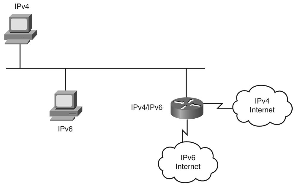
Figure 10-19 illustrates an example of a router with both IPv4 and IPv6 addresses connected to a network that is running both protocols.
Figure 10-19
When Both IPv4 and IPv6 Addresses Are Configured, the Interface Is Dual-Stacked
Tunneling
Tunnels are often used in networking to overlay incompatible functions over an existing network. For IPv6, tunneling is an integration method in which an IPv6 packet is encapsulated within another protocol, such as IPv4. Tunneling IPv6 inside of IPv4 uses IPv4 protocol 41. When tunneling IPv6 traffic over an IPv4 network, one edge router encapsulates the IPv6 packet inside an IPv4 packet and the router at the other edge decapsulates it, and vice versa. This enables the connection of IPv6 islands without the need to convert the intermediary network to IPv6.
As illustrated in Figure 10-20, a 20-byte IPv4 header (if there are not any options in the header) is included before the IPv6 header and payload (data). The routers involved are dual stacking.
Figure 10-20
Tunneling IPv6 Inside IPv4 Packets
When tunneling, the MTU is effectively decreased by 20 octets (or more if the IPv4 header contains any optional fields). Because of this restriction and the fact that a tunneled network is often difficult to troubleshoot, tunneling is an intermediate integration/transition technique that should not be considered a final solution. A native IPv6 network should be the ultimate goal.
Tunneling can be done by edge routers either between hosts as shown in Figure 10-20, or between a host and a router, as shown in Figure 10-21. In Figure 10-21, an isolated dual-stack host uses an encapsulated tunnel to connect to the edge router of the IPv6 network.
Figure 10-21
Isolated Dual-Stack Host
Note that tunneling will not work if an intermediary node between the two end points of the tunnel, such as a firewall, filters out IPv4 protocol 41, the IPv6 in IPv4 encapsulation protocol.
Configured tunnels require dual-stack end points and IPv4 and IPv6 addresses configured at each end, as illustrated in Figure 10-22.
Figure 10-22
Tunneling Requires IPv6 and IPv4 Configured at Each End
Tunnels can be either manually or automatically configured.
Manually Configured Tunnels
For a manually configured tunnel, you configure both the IPv4 and IPv6 addresses statically on the routers at each end of the tunnel.
The end routers must be dual-stacked, and the configuration will not change dynamically as network and routing needs change. IPv4 routing must be set up properly to forward a packet between the two IPv6 networks.
The interfaces used as tunnel end points can be unnumbered, but unnumbered interfaces make troubleshooting more difficult. The IPv4 practice of using unnumbered interfaces to save address space is no longer an issue.
Figure 10-23 shows two routers connecting IPv6 networks through IPv4 encapsulation. Example 10-12 and Example 10-13 provide the configurations for the two routers.
Network Used to Illustrate Tunnel Configuration
Example 10-12 Configuration of Router 1 in Figure 10-23
interface Tunnel0
 ipv6 address 2001:db8:1::1/64
 tunnel source 192.168.2.1
 tunnel destination 192.168.30.1
 tunnel mode ipv6ip
Example 10-13 Configuration of Router 2 in Figure 10-23
interface Tunnel0
 ipv6 address 2001:db8:1::2/64
 tunnel source 192.168.30.1
 tunnel destination 192.168.2.1
 tunnel mode ipv6ip
The command interface Tunnel0 creates the tunnel interface, on which a static IPv6 address is configured with the ipv6 address command. The tunnel source and tunnel destination commands specify the IPv4 source and destination addresses of the tunnel, respectively. These are addresses in the underlying IPv4 network. The tunnel mode ipv6ip command specifies a manual IPv6 tunnel with IPv6 as the passenger protocol, and IPv4 as both the encapsulation and transport protocol.
The clear counters tunnel interface-number command clears the counters displayed in the show interface tunnel command.
Other Tunneling Mechanisms
Several automatic tunneling transition mechanisms exist, including the following:
6-to-4—This mechanism uses the reserved prefix 2002::/16 to allow an IPv4-connected site to create and use a /48 IPv6 prefix based on a single globally routable/reachable IPv4 address. 6-to-4 tunneling is described further in the next section, “6-to-4 Tunneling.”
Intra-Site Automatic Tunnel Addressing Protocol (ISATAP)—ISATAP allows an IPv4 private intranet (that may or may not be using RFC 1918 addresses) to incrementally implement IPv6 nodes without upgrading the network.
Teredo (formerly known as shipworm)—This mechanism tunnels IPv6 datagrams within IPv4 UDP datagrams, allowing private IPv4 address and IPv4 NAT traversal to be used.
6-to-4 Tunneling
The 6-to-4 tunneling method automatically connects IPv6 islands through an IPv4 network, as illustrated in Figure 10-24.
Figure 10-24
6-to-4 Tunnels Are Built Automatically by the Edge Routers
Each 6-to-4 edge router has an IPv6 address with a /48 prefix, which is the concatenation of 2002::/16 and the hexadecimal representation of the IPv4 address of the edge router; 2002::/16 is a specially assigned address range for the purpose of 6-to-4 tunneling. The edge routers automatically build the tunnel using the IPv4 addresses that are embedded in the IPv6 addresses. For example, if the IPv4 address of an edge router is 192.168.99.1, the prefix of its IPv6 address is 2002:c0a8:6301::/48, because 0xc0a86301 is the hexadecimal representation of 192.168.99.1.
6-to-4 tunnels enable the fast deployment of IPv6 in a corporate network without the need for addresses from ISPs or registries. The 6-to-4 tunneling method requires special code on the edge routers, but the IPv6 hosts and routers inside of the 6-to-4 site do not require new features.
When the edge router receives an IPv6 packet with a destination address in the range of 2002::/16, it determines from its routing table that the packet must traverse the tunnel. The router extracts the IPv4 address embedded in the third to sixth octets, inclusively, in the IPv6 next-hop address. This IPv4 address is the IPv4 address of the 6-to-4 router at the destination site—the router at the other end of the tunnel. The router encapsulates the IPv6 packet in an IPv4 packet with the destination edge router’s extracted IPv4 address.
The packet passes through the IPv4 network. The destination edge router decapsulates the IPv6 packet from the received IPv4 packet and forwards the IPv6 packet to its final destination. (A 6-to-4 relay router, which offers traffic forwarding to the IPv6 Internet, is required for reaching a native IPv6 Internet.)
Translation Mechanisms
Dual stack and tunneling techniques manage the interconnection of IPv6 domains. For legacy equipment that will not be upgraded to IPv6 and for some deployment scenarios, techniques are available for connecting IPv4-only nodes to IPv6-only nodes using translation, an extension of NAT techniques.
As shown in Figure 10-25, NAT-PT is a translation mechanism that sits between an IPv6 network and an IPv4 network. The job of the translator is to translate IPv6 packets into IPv4 packets and vice versa.

Figure 10-25
IPv4 – IPv6 Translation Mechanism
The Stateless IP/ICMP Translation (SIIT) algorithm translates the IP header fields, while NAT handles the IP address translation. Figure 10-25 shows static NAT-PT translations; NAT-PT translations may also be mapped dynamically based on DNS queries using a DNS-application layer gateway (DNS-ALG). ALGs use a dual-stack approach and enable a host in an IPv6-only domain to send data to another host in an IPv4-only domain. This method requires that all application servers run IPv6.
The example in Figure 10-25 illustrates the translation of an IPv6 datagram sent from node A to node D. From the perspective of node A, it is establishing a communication to another IPv6 node. One advantage of NAT-PT is that no modifications are required on IPv6 node A; all it needs to know is the IPv6 address mapping of the IPv4 address of node D. This mapping can be obtained dynamically from the DNS server. IPv4 node D can also send a datagram to node A by using the IPv4 address mapped to the IPv6 address of node A. Again, from the perspective of node D, it is establishing IPv4 communication with node A; node D does not require modification.
APIs can be installed in a host’s TCP/IP stack to intercept IP traffic through the API and convert it for the IPv6 counterpart.
Bump-in-the-API (BIA) and Bump-in-the-Stack (BIS) are localized implementations of NAT-PT. They provide support for translation from upper layers that are IPv4-only down through the Open Systems Interconnection (OSI) layers. These implementations intercept either API calls or packets in the stack and translate them on the fly. Only IPv6 packets will travel out on the network. Not all applications will work with BIA or BIS solutions though. For example, file transfer protocol (FTP), which embeds IP addresses in the packet payload, would not work because the outer IP addresses and packets would be translated by BIA or BIS, but the embedded IPv6 addresses would not be translated when going back up the stack.
Summary
In this chapter, you learned the basics of IPv6; the following topics were presented:
The need for IPv6’s larger address space as IPv4 addresses are exhausted
IPv6 packet structure, including the use of extension headers
IPv6 address representation, including the three types of addresses: unicast, anycast, and multicast
The EUI-64 format for representing interface identifiers
How IPv6’s stateless autoconfiguration feature works
IPv6 support for IP mobility
The routing protocols available for IPv6, including RIPng, OSPFv3, IS-IS for IPv6, EIGRP for IPv6, and MP-BGP4
How to enable IPv6 and how to configure IPv6 interface addresses
The features of and how to configure and verify OSPF for IPv6
The mechanisms available for the transition from IPv4 to IPv6, including dual stack, tunneling, and translation
References
For additional information, refer to the following resources:
The Cisco IOS IPv6 Configuration Guide, Release 12.4, available at https://www.cisco.com/en/US/products/ps6350/products_configuration_guide_book09186a0080435e8c.html
IPv6 Multicast at-a-glance, available at https://www.cisco.com/application/pdf/en/us/guest/tech/tk872/c1482/cdccont_0900aecd80260049.pdf
Configuration Exercise 10-1: Configuring IPv6 Addresses and OSPF for IPv6 Routing
In this Configuration Exercise, you enable IPv6 routing globally, configure IPv6 addresses on your pod routers, and enable IPv6 OSPF routing.
Introduction to the Configuration Exercises – This book uses Configuration Exercises to help you practice configuring routers with the commands and topics presented. If you have access to real hardware, you can try these exercises on your routers. See Appendix B, “Configuration Exercise Equipment Requirements and Backbone Configurations,” for a list of recommended equipment and initial configuration commands for the backbone routers. However, even if you do not have access to any routers, you can go through the exercises, and keep a log of your own running configurations, or just read through the solution. Commands used and solutions to the Configuration Exercises are provided within the exercises.
In the Configuration Exercises, the network is assumed to consist of two pods, each with four routers. The pods are interconnected to a backbone. You configure pod 1. No interaction between the two pods is required, but you might see some routes from the other pod in your routing tables in some exercises if you have it configured. In most of the exercises, the backbone has only one router; in some cases, another router is added to the backbone. Each Configuration Exercise assumes that you have completed the previous chapters’ Configuration Exercises on your pod.
Throughout this exercise, the pod number is referred to as x, and the router number is referred to as y. Substitute the appropriate numbers as needed.
Objectives
The objectives of this exercise are to enable IPv6 globally and on an interface, and to enable IPv6 OSPF routing.
Visual Objective
Figure 10-26 illustrates the topology used in this exercise. The format for the IPv6 addresses used in this exercise is 2001:0410:000x:z::/64 eui-64, where
x = pod number
z = 1 for the FastEthernet 0/0 interfaces between PxR1 and PxR3
z = 2 for the FastEthernet 0/0 interfaces between PxR2 and PxR4
z = 3 for the Serial 0/0/1 interfaces between PxR1 and PxR2
z = 4 for the Serial 0/0/0 interfaces between PxR3 and PxR4
The IPv4 addresses remain in place.

Figure 10-26
IPv6 Addressing Configuration Exercise Topology
Command List
In this exercise, you use the commands in Table 10-9, listed in logical order. Refer to this list if you need configuration command assistance during the exercise.
Caution – Although the command syntax is shown in this table, the addresses shown are typically for the PxR1 and PxR3 routers. Be careful when addressing your routers! Refer to the exercise instructions and the appropriate visual objective diagram for addressing details.
Table 10-9 IPv6 Addressing Configuration Exercise Commands
| Command | Description |
|---|---|
| (config)#ipv6 unicast-routing | Enables IPv6 traffic forwarding. |
| (config)#ipv6 cef | Enables CEFv6. |
| (config-if)# ipv6 address 2001:0410:000x:z::/64 eui-64 | Enables an IPv6 address on an interface (with the format specified earlier in this exercise) and forces the router to complete the addresses’ low-order 64-bit by using the interface’s link-layer address (MAC address) in EUI-64 format. |
| #show ipv6 interface | Displays IPv6 information about an interface. |
| (config)#ipv6 router ospf 100 | Enables the OSPFv3 process 100 on the router. |
| (config-rtr)#router-id 10.200.200.xy | Defines the OSPF router-id. |
| (config-if)#ipv6 ospf 100 area 0 | Identifies the IPv6 prefix assigned to this interface as part of the OSPFv3 network for process-id 100 in area 0. |
| #show ipv6 ospf interface | Displays IPv6 OSPF information about an interface. |
| #show ipv6 ospf neighbor | Displays IPv6 OSPF neighbor information. |
| #show ipv6 route | Displays the IPv6 routing table. |
| #show cdp neighbor detail | Displays detailed CDP neighbor information. |
| #show ipv6 interface brief | Displays a brief list of IPv6 interface information. |
Task 1: Cleaning Up
In this task, you remove the multicast routing configuration and isolate the pod from the backbone routers.
Follow these steps:
Remove the multicast configuration from all the pod routers using the no ip multicast-routing global configuration command. Remove the multicast configuration from all interfaces it was enabled on using the no ip pim sparse-dense-mode command.
On PxR1, remove the auto-rp configuration with the no ip pim send-rp-announce loopback0 scope 3 command and the no ip pim send-rp-discovery loopback0 scope 3 command.
On the FastEthernet 0/0 interface on PxR4, disable join messages with the no ip igmp join-group 224.x.x.x command, where x is your pod number.
On the edge routers, shut down Serial 0/0/0; IPv6 will not be used to the core.
Solution:
The following shows how to do the required steps on the P1R1 and P1R4 routers:
P1R1(config)#no ip multicast-routing
P1R1(config)#int loopback0
P1R1(config-if)#no ip pim sparse-dense-mode
P1R1(config-if)#int fa0/0
P1R1(config-if)#no ip pim sparse-dense-mode
P1R1(config-if)#int s0/0/0.1
P1R1(config-subif)#no ip pim sparse-dense-mode
P1R1(config-subif)#int s0/0/1
P1R1(config-if)#no ip pim sparse-dense-mode
P1R1(config-if)#exit
P1R1(config)#no ip pim send-rp-announce Loopback0 scope 3
P1R1(config)#no ip pim send-rp-discovery Loopback0 scope 3
P1R1(config)#int s0/0/0
P1R1(config-if)#shutdown

P1R4(config)#no ip multicast-routing
P1R4(config)#int loopback0
P1R4(config-if)#no ip pim sparse-dense-mode
P1R4(config-if)#int fa0/0
P1R4(config-if)#no ip pim sparse-dense-mode
P1R4(config-if)#int s0/0/0
P1R4(config-if)#no ip pim sparse-dense-mode
P1R4(config-if)#int fa0/0
P1R4(config-if)#no ip igmp join-group 224.1.1.1
Task 2: Configuring IPv6
In this task, you enable IPv6 globally on your router and configure IPv6 addresses on all interfaces that are not shut down.
In this task, the FastEthernet interfaces will use the following address format: 2001:0410:000x:1::/64 eui-64 or 2001:0410:000x:2::/64 eui-64, where
x = pod number
:1 is for odd router numbers (PxR1 and PxR3)
:2 is for even router numbers (PxR2 and PxR4)
For example, on P1R4, the Fa0/0 IPv6 address would be: 2001:0410:0001:2::/64. The :1 or :2 is the subnet portion of your IPv6 address, so it is important, for example, that PxR1 and PxR3’s Fa0/0 interfaces are in the same subnet.
The Serial 0/0/1 interfaces for the edge routers and the Serial 0/0/0 for the internal routers will use the following address format: 2001:0410:000x:3::/64 eui-64 or 2001:0410:000x:4::/64 eui-64, where
x = pod number
:3 is for the edge routers (PxR1 and PxR2)
:4 is for the internal routers (PxR3 and PxR4)
For example, on P1R1, the S0/0/1 IPv6 address would be: 2001:0410:0001:3::/64. The :3 or :4 is the subnet portion of your IPv6 address on the serial interface.
Write down the IPv6 addresses for each of your routers in Table 10-10.
Table 10-10 IPv6 Addresses
| Router | Fa0/0 Address | S0/0/0 or S0/0/1 Address |
|---|---|---|
| PxR1 | ||
| PxR2 | ||
| PxR3 | ||
| PxR4 |
Follow these steps:
Configure the edge and internal routers as follows:
Enable IPv6 and CEFv6 on all routers in each pod.
Configure an IPv6 global address on all Fa0/0 interfaces.
Configure an IPv6 global address on the S0/0/1 interfaces on edge routers and the S0/0/0 interfaces on internal routers.
Solution:
The following shows the required steps on the P1R1 router:
P1R1(config)#ipv6 unicast-routing
P1R1(config)#ipv6 cef
P1R1(config)#int fa0/0
P1R1(config-if)#ipv6 address 2001:0410:0001:1::/64 eui-64
P1R1(config-if)#int s0/0/1
P1R1(config-if)#ipv6 address 2001:0410:0001:3::/64 eui-64
Display the IPv6 interface information to verify that the appropriate interfaces on all routers are configured with an IPv6 address.
On the interfaces, do you see an IPv6 address that you have not configured? If so, what is that address?
Solution:
The following shows sample output on the P1R1 router. IPv6 addresses have been configured, with the specified prefix and the interface ID in EUI-64 format. A link-local address has also been configured on the interfaces; for example on P1R1 Fa0/0, the link-local address is FE80::216:46FF:FE50:C470.
P1R1#show ipv6 interface
FastEthernet0/0 is up, line protocol is up
 IPv6 is enabled, link-local address is FE80::216:46FF:FE50:C470
 No Virtual link-local address(es):
 Global unicast address(es):
  2001:410:1:1:216:46FF:FE50:C470, subnet is 2001:410:1:1::/64 [EUI]
 Joined group address(es):
  FF02::1
  FF02::2
  FF02::1:FF50:C470
 MTU is 1500 bytes
 ICMP error messages limited to one every 100 milliseconds
 ICMP redirects are enabled
 ICMP unreachables are sent
 ND DAD is enabled, number of DAD attempts: 1
 ND reachable time is 30000 milliseconds
 ND advertised reachable time is 0 milliseconds
 ND advertised retransmit interval is 0 milliseconds
 ND router advertisements are sent every 200 seconds
 ND router advertisements live for 1800 seconds
 ND advertised default router preference is Medium
 Hosts use stateless autoconfig for addresses.
Serial0/0/1 is up, line protocol is up
 IPv6 is enabled, link-local address is FE80::216:46FF:FE50:C470
 No Virtual link-local address(es):
 Global unicast address(es):
  2001:410:1:3:216:46FF:FE50:C470, subnet is 2001:410:1:3::/64 [EUI]
 Joined group address(es):
  FF02::1
  FF02::2
  FF02::1:FF50:C470
 MTU is 1500 bytes
 ICMP error messages limited to one every 100 milliseconds
 ICMP redirects are enabled
 ICMP unreachables are sent
 ND DAD is enabled, number of DAD attempts: 1
 ND reachable time is 30000 milliseconds
 Hosts use stateless autoconfig for addresses.
P1R1#
Task 3: Enable IPv6 OSPF
In this task, you enable IPv6 OSPF on all pod routers.
Follow these steps:
On each router in your pod, globally enable OSPF for IPv6 and configure the router ID to be the same value as the loopback 0 interface’s IPv4 address.
Enable IPv6 OSPF in area 0 on all enabled FastEthernet and Serial interfaces (those that are not shut down).
Solution:
The following shows the required steps on the P1R1 router:
P1R1(config)#ipv6 router ospf 100
P1R1(config-rtr)#router-id 10.200.200.11
P1R1(config-rtr)#int fa0/0
P1R1(config-if)#ipv6 ospf 100 area 0
P1R1(config-if)#int s0/0/1
P1R1(config-if)#ipv6 ospf 100 area 0
Display the IPv6 OSPF interface information to confirm that you have enabled OSPF for IPv6 on your routers.
Solution:
The following shows sample output on the P1R1 router; OSPF for IPv6 is enabled on all interfaces, with process ID 100 in area0.
P1R1#show ipv6 ospf interface
Serial0/0/1 is up, line protocol is up
 Link Local Address FE80::216:46FF:FE50:C470, Interface ID 7
 Area 0, Process ID 100, Instance ID 0, Router ID 10.200.200.11
 Network Type POINT_TO_POINT, Cost: 781
 Transmit Delay is 1 sec, State POINT_TO_POINT,
 Timer intervals configured, Hello 10, Dead 40, Wait 40, Retransmit 5
  Hello due in 00:00:09
 Index 1/2/2, flood queue length 0
 Next 0x0(0)/0x0(0)/0x0(0)
 Last flood scan length is 1, maximum is 4
 Last flood scan time is 0 msec, maximum is 0 msec
 Neighbor Count is 1, Adjacent neighbor count is 1
  Adjacent with neighbor 10.200.200.12
 Suppress hello for 0 neighbor(s)
FastEthernet0/0 is up, line protocol is up
 Link Local Address FE80::216:46FF:FE50:C470, Interface ID 4
 Area 0, Process ID 100, Instance ID 0, Router ID 10.200.200.11
 Network Type BROADCAST, Cost: 1
 Transmit Delay is 1 sec, State DR, Priority 1
 Designated Router (ID) 10.200.200.11, local address FE80::216:46FF:FE50:C470
 Backup Designated router (ID) 10.200.200.13, local address FE80::216:46FF:FE10
:FDB0
 Timer intervals configured, Hello 10, Dead 40, Wait 40, Retransmit 5
  Hello due in 00:00:03
 Index 1/1/1, flood queue length 0
 Next 0x0(0)/0x0(0)/0x0(0)
 Last flood scan length is 1, maximum is 4
 Last flood scan time is 0 msec, maximum is 0 msec
 Neighbor Count is 1, Adjacent neighbor count is 1
  Adjacent with neighbor 10.200.200.13 (Backup Designated Router)
 Suppress hello for 0 neighbor(s)
Verify that you see your OSPFv3 neighbors.
Solution:
The following shows sample output on the P1R1 router; both neighbors are displayed.
P1R1#show ipv6 ospf neighbor

Neighbor ID   Pri  State      Dead Time  Interface ID Interface
10.200.200.12   1  FULL/ -    00:00:30  7       Serial0/0/1
10.200.200.13   1  FULL/BDR    00:00:36  4       FastEthernet0/0
P1R1#
View the IPv6 routing table on your routers.
Solution:
The following shows sample output on the P1R1 router.
P1R1#show ipv6 route
IPv6 Routing Table - 8 entries
Codes: C - Connected, L - Local, S - Static, R - RIP, B - BGP
    U - Per-user Static route
    I1 - ISIS L1, I2 - ISIS L2, IA - ISIS interarea, IS - ISIS summary
    O - OSPF intra, OI - OSPF inter, OE1 - OSPF ext 1, OE2 - OSPF ext 2
    ON1 - OSPF NSSA ext 1, ON2 - OSPF NSSA ext 2
C  2001:410:1:1::/64 [0/0]
   via ::, FastEthernet0/0
L  2001:410:1:1:216:46FF:FE50:C470/128 [0/0]
   via ::, FastEthernet0/0
O  2001:410:1:2::/64 [110/782]
   via FE80::216:46FF:FE10:FC00, Serial0/0/1
C  2001:410:1:3::/64 [0/0]
   via ::, Serial0/0/1
L  2001:410:1:3:216:46FF:FE50:C470/128 [0/0]
   via ::, Serial0/0/1
O  2001:410:1:4::/64 [110/782]
   via FE80::216:46FF:FE10:FDB0, FastEthernet0/0
L  FE80::/10 [0/0]
   via ::, Null0
L  FF00::/8 [0/0]
   via ::, Null0
P1R1#
If you can see the neighboring router’s IPv6 networks in the routing table, you should be able to ping their IPv6 addresses. To make pinging of IPv6 addresses simpler, find the IPv6 addresses of each of the enabled interfaces on all the routers in your pod and copy and paste them into Notepad. Use the show cdp neighbor detail command to display the IPv6 addresses of your immediate neighbors or the show ipv6 interface brief command to display the IPv6 address of the router you are on.
After you have documented the IPv6 addresses, you can simply copy and paste the address into your terminal program when you want to ping one of your neighboring routers’ IPv6 interfaces. Ping all the IPv6 addresses in your pod.
Solution:
The following shows an example of the display of the IPv6 addresses on the P1R2 router, and pings to those addresses from the P1R1 router. The pings are successful.
P1R2#show ipv6 interface brief
FastEthernet0/0      [up/up]
  FE80::216:46FF:FE10:FC00
  2001:410:1:2:216:46FF:FE10:FC00
FastEthernet0/1      [administratively down/down]
  unassigned
Serial0/0/0        [administratively down/down]
  unassigned
Serial0/0/0.1       [administratively down/down]
  unassigned
Serial0/0/0.2       [administratively down/down]
  unassigned
Serial0/0/1        [up/up]
  FE80::216:46FF:FE10:FC00
  2001:410:1:3:216:46FF:FE10:FC00
Loopback0         [up/up]
  Unassigned
P1R2#

P1R1#ping 2001:410:1:2:216:46FF:FE10:FC00

Type escape sequence to abort.
Sending 5, 100-byte ICMP Echos to 2001:410:1:2:216:46FF:FE10:FC00, timeout is 2
seconds:
!!!!!
Success rate is 100 percent (5/5), round-trip min/avg/max = 28/28/28 ms
P1R1#ping 2001:410:1:3:216:46FF:FE10:FC00

Type escape sequence to abort.
Sending 5, 100-byte ICMP Echos to 2001:410:1:3:216:46FF:FE10:FC00, timeout is 2
seconds:
!!!!!
Success rate is 100 percent (5/5), round-trip min/avg/max = 28/28/28 ms
P1R1#
Save your configurations to NVRAM.
Solution:
The following shows the required step on the P1R1 router.
P1R1#copy run start
Destination filename [startup-config]?
Building configuration...
[OK]
Exercise Verification
You have successfully completed this exercise when you have enabled IPv6 routing globally, configured IPv6 addresses on your pod routers, and enabled and verified IPv6 OSPF routing.
Configuration Exercise 10-2: Configuring an IPv6 Tunnel
In this Configuration Exercise, you configure a manual IPv6 tunnel.
Note – Throughout this exercise, the pod number is referred to as x, and the router number is referred to as y. Substitute the appropriate numbers as needed.
Objectives
The objectives of this exercise are to configure a manual IPv6 tunnel.
Visual Objective
Figure 10-27 illustrates the topology used and what you will accomplish in this exercise.
IPv6 Tunnel Configuration Exercise Topology
Command List
In this exercise, you use the commands in Table 10-11, listed in logical order. Refer to this list if you need configuration command assistance during the exercise.
Although the command syntax is shown in this table, the addresses shown are typically for the PxR1 and PxR3 routers. Be careful when addressing your routers! Refer to the exercise instructions and the appropriate visual objective diagram for addressing details.
Table 10-11 IPv6 Tunnel Configuration Exercise Commands
| Command | Description |
|---|---|
| (config)#interface tunnel 0 | Specifies a tunnel interface number (0) on which to enable a configured tunnel. |
| (config-if)#ipv6 address 2001:410:x:A::y/64 | Statically assigns an IPv6 address and a prefix length to the tunnel interface. |
| (config-if)#tunnel source 10.x.0.y | Defines the local IPv4 address used as the source address for the tunnel interface. |
| (config-if)#tunnel destination 10.x.0.y | Defines the tunnel endpoint’s destination IPv4 address; in other words, the address of the remote end of the tunnel. |
| (config-if)#tunnel mode ipv6ip | Specifies a manual IPv6 tunnel. |
| (config-if)#ipv6 ospf 100 area 0 | Identifies the IPv6 prefix assigned to this interface as part of the OSPFv3 network for process 100 in area 0. |
| #show interface tunnel 0 | Displays information about the tunnel 0 interface. |
| #show run | begin interface Tunnel | Displays the running configuration, starting at the words “interface Tunnel.” |
| #show ipv6 route | Displays the IPv6 routing table. |
| #clear counters tunnel 0 | Clears the counters displayed in the show interface tunnel 0 command. |
Task: Configuring the Tunnel Interface
In this task, you prepare the IPv4 tunnel interface to carry IPv6 packets.
Follow these steps:
On the internal routers disable your serial 0/0/0 interfaces. Only the edge routers will be configured with the manual tunnel on their serial 0/0/1 interfaces.
Remove the IPv6 address from the S0/0/1 interfaces on the edge routers.
Create a tunnel and put both ends of the tunnel (PxR1 and PxR2) in the same IPv6 subnet, 2001:410:x:A::y/64, where x is your pod number and y is your router number. Configure the tunnel source and tunnel destination at both ends of the tunnel; for example, PxR1 points to PxR2’s serial interface for the tunnel destination and its own serial interface for the tunnel source. Configure the tunnel mode for a manual IPv6 tunnel. Enable IPv6 OSPF routing on the tunnel interface.
Solution:
The following shows how to configure the required steps on the P1R1, P1R2, and P1R3 routers.
P1R1(config)#int s0/0/1
P1R1(config-if)#no ipv6 address
P1R1(config-if)#int tunnel0
P1R1(config-if)#ipv6 address 2001:410:1:A::1/64
P1R1(config-if)#tunnel source 10.1.0.1
P1R1(config-if)#tunnel destination 10.1.0.2
P1R1(config-if)#tunnel mode ipv6ip
P1R1(config-if)#ipv6 ospf 100 area 0

P1R2(config)#int s0/0/1
P1R2(config-if)#no ipv6 address
P1R2(config)#int tunnel 5
P1R2(config-if)#ipv6 address 2001:410:1:A::2/64
P1R2(config-if)#tunnel source 10.1.0.2
P1R2(config-if)#tunnel destination 10.1.0.1
P1R2(config-if)#tunnel mode ipv6ip
P1R2(config-if)#ipv6 ospf 100 area 0

P1R3(config)#int s0/0/0
P1R3(config-if)#shutdown
Confirm your configuration by displaying information about the tunnel interface on your edge routers.
Solution:
The following shows sample output on the P1R1 router. The tunnel is up.
P1R1#show int tunnel 0
Tunnel0 is up, line protocol is up
 Hardware is Tunnel
 MTU 1514 bytes, BW 9 Kbit, DLY 500000 usec,
   reliability 255/255, txload 1/255, rxload 1/255
 Encapsulation TUNNEL, loopback not set
 Keepalive not set
 Tunnel source 10.1.0.1, destination 10.1.0.2
 Tunnel protocol/transport IPv6/IP
 Tunnel TTL 255
 Fast tunneling enabled
 Tunnel transmit bandwidth 8000 (kbps)
 Tunnel receive bandwidth 8000 (kbps)
 Last input 00:00:06, output 00:00:00, output hang never
 Last clearing of "show interface" counters never
 Input queue: 0/75/0/0 (size/max/drops/flushes); Total output drops: 0
 Queueing strategy: fifo
 Output queue: 0/0 (size/max)
 5 minute input rate 0 bits/sec, 0 packets/sec
 5 minute output rate 0 bits/sec, 0 packets/sec
   26 packets input, 3500 bytes, 0 no buffer
   Received 0 broadcasts, 0 runts, 0 giants, 0 throttles
   0 input errors, 0 CRC, 0 frame, 0 overrun, 0 ignored, 0 abort
   47 packets output, 4972 bytes, 0 underruns
   0 output errors, 0 collisions, 0 interface resets
   0 output buffer failures, 0 output buffers swapped out
P1R1#
Use the show run | begin interface Tunnel command to see your tunnel configuration
Solution:
The following shows sample output on the P1R1 router.
P1R1# show run | begin interface Tunnel
interface Tunnel0
 no ip address
 ipv6 address 2001:410:1:A::1/64
 ipv6 ospf 100 area 0
 tunnel source 10.1.0.1
 tunnel destination 10.1.0.2
 tunnel mode ipv6ip
!
Look at your IPv6 routing table. Are you learning an OSPF route over the tunnel?
Solution:
The following shows sample output on the P1R1 router. An OSPF route is being learned over the tunnel.
P1R1#show ipv6 route
IPv6 Routing Table - 7 entries
Codes: C - Connected, L - Local, S - Static, R - RIP, B - BGP
    U - Per-user Static route
    I1 - ISIS L1, I2 - ISIS L2, IA - ISIS interarea, IS - ISIS summary
    O - OSPF intra, OI - OSPF inter, OE1 - OSPF ext 1, OE2 - OSPF ext 2
    ON1 - OSPF NSSA ext 1, ON2 - OSPF NSSA ext 2
C  2001:410:1:1::/64 [0/0]
   via ::, FastEthernet0/0
L  2001:410:1:1:216:46FF:FE50:C470/128 [0/0]
   via ::, FastEthernet0/0
O  2001:410:1:2::/64 [110/11112]
   via FE80::A01:2, Tunnel0
C  2001:410:1:A::/64 [0/0]
   via ::, Tunnel0
L  2001:410:1:A::1/128 [0/0]
   via ::, Tunnel0
L  FE80::/10 [0/0]
   via ::, Null0
L  FF00::/8 [0/0]
   via ::, Null0
P1R1#
At this point, you should be able to ping across your tunnel. Use the IPv6 addresses that you copied in the previous configuration exercise to see whether packets can go across the tunnel. For example, on PxR1 ping the Fa0/0 interface of PxR2, and on PxR2, ping the Fa0/0 of PXR1.
Solution:
The following shows sample output on the P1R1 and P1R2 routers. In the first sample, P1R1 is pinging P1R2’s Fa0/0 interface. In the second sample, P1R2 is pinging P1R1’s Fa0/0 interface. Both pings are successful.
P1R1#ping 2001:410:1:2:216:46FF:FE10:FC00

Type escape sequence to abort.
Sending 5, 100-byte ICMP Echos to 2001:410:1:2:216:46FF:FE10:FC00, timeout is 2
seconds:
!!!!!
Success rate is 100 percent (5/5), round-trip min/avg/max = 32/33/36 ms
P1R1#

P1R2#ping 2001:410:1:1:216:46FF:FE50:C470

Type escape sequence to abort.
Sending 5, 100-byte ICMP Echos to 2001:410:1:1:216:46FF:FE50:C470, timeout is 2
seconds:
!!!!!
Success rate is 100 percent (5/5), round-trip min/avg/max = 32/34/36 ms
P1R2#
To confirm that the traffic is going through the tunnel, clear the counters on the tunnel interface. Display information about the tunnel again, then ping the IPv6 address again, and then display information about the tunnel once more. Did you notice a difference in the displayed information? If so, what?
Solution:
The following shows sample output on the P1R1 router. The counters on the interface increased after the ping.
P1R1#clear counters tunnel 0
Clear "show interface" counters on this interface [confirm]
P1R1#
*Jul 10 01:58:18.295: %CLEAR-5-COUNTERS: Clear counter on interface Tunnel0 by console

P1R1#show int tunnel 0
Tunnel0 is up, line protocol is up
 Hardware is Tunnel
 MTU 1514 bytes, BW 9 Kbit, DLY 500000 usec,
   reliability 255/255, txload 1/255, rxload 1/255
 Encapsulation TUNNEL, loopback not set
 Keepalive not set
 Tunnel source 10.1.0.1, destination 10.1.0.2
 Tunnel protocol/transport IPv6/IP
 Tunnel TTL 255
 Fast tunneling enabled
 Tunnel transmit bandwidth 8000 (kbps)
 Tunnel receive bandwidth 8000 (kbps)
 Last input 00:00:01, output 00:00:05, output hang never
 Last clearing of "show interface" counters 00:00:05
 Input queue: 0/75/0/0 (size/max/drops/flushes); Total output drops: 0
 Queueing strategy: fifo
 Output queue: 0/0 (size/max)
 5 minute input rate 0 bits/sec, 0 packets/sec
 5 minute output rate 0 bits/sec, 0 packets/sec
   1 packets input, 120 bytes, 0 no buffer
   Received 0 broadcasts, 0 runts, 0 giants, 0 throttles
   0 input errors, 0 CRC, 0 frame, 0 overrun, 0 ignored, 0 abort
   0 packets output, 0 bytes, 0 underruns
   0 output errors, 0 collisions, 0 interface resets
   0 output buffer failures, 0 output buffers swapped out

P1R1#ping 2001:410:1:2:216:46FF:FE10:FC00

Type escape sequence to abort.
Sending 5, 100-byte ICMP Echos to 2001:410:1:2:216:46FF:FE10:FC00, timeout is 2 seconds:
!!!!!
Success rate is 100 percent (5/5), round-trip min/avg/max = 32/34/36 ms

P1R1#show int tunnel 0
Tunnel0 is up, line protocol is up
 Hardware is Tunnel
 MTU 1514 bytes, BW 9 Kbit, DLY 500000 usec,
   reliability 255/255, txload 1/255, rxload 28/255
 Encapsulation TUNNEL, loopback not set
 Keepalive not set
 Tunnel source 10.1.0.1, destination 10.1.0.2
 Tunnel protocol/transport IPv6/IP
 Tunnel TTL 255
 Fast tunneling enabled
 Tunnel transmit bandwidth 8000 (kbps)
 Tunnel receive bandwidth 8000 (kbps)
 Last input 00:00:04, output 00:00:04, output hang never
 Last clearing of "show interface" counters 00:00:28
 Input queue: 0/75/0/0 (size/max/drops/flushes); Total output drops: 0
 Queueing strategy: fifo
 Output queue: 0/0 (size/max)
 5 minute input rate 1000 bits/sec, 1 packets/sec
 5 minute output rate 0 bits/sec, 1 packets/sec
   8 packets input, 1060 bytes, 0 no buffer
   Received 0 broadcasts, 0 runts, 0 giants, 0 throttles
   0 input errors, 0 CRC, 0 frame, 0 overrun, 0 ignored, 0 abort
   7 packets output, 800 bytes, 0 underruns
   0 output errors, 0 collisions, 0 interface resets
   0 output buffer failures, 0 output buffers swapped out
P1R1#
Save your configurations to NVRAM.
Solution:
The following shows the required step on the P1R1 router.
P1R1#copy run start
Destination filename [startup-config]?
Building configuration...
[OK]
Exercise Verification
You have successfully completed this exercise when you have created a manual IPv6 to IPv4 tunnel and pinged across it.
Review Questions
Answer the following questions, and then refer to Appendix A, “Answers to Review Questions,” for the answers.
What are some of the features of IPv6?
How many bits are in an IPv6 address?
How long is the basic IPv6 packet header?
What is the flow label in the IPv6 packet header used for?
Does the IPv6 packet header have a checksum field?
In general which node processes IPv6 extension headers?
In what format are IPv6 addresses written?
Which of the following are valid representations of the IPv6 address 2035:0001:2BC5:0000:0000:087C:0000:000A?
2035:0001:2BC5::087C::000A
2035:1:2BC5::87C:0:A
2035:0001:2BC5::087C:0000:000A
2035:1:2BC5:0:0:87C::A
2035:1:2BC5::087C:A
What is the format of an IPv6 broadcast address?
Which of the following are the true statements?
A packet that is sent to an IPv6 anycast address goes to the closest interface identified by that address.
A packet that is sent to an IPv6 anycast address goes to all interfaces identified by that address.
A packet that is sent to an IPv6 multicast address goes to the closest interface identified by that address.
A packet that is sent to an IPv6 multicast address goes to all interfaces identified by that address.
How is an IPv6 interface identifier created for Ethernet interfaces?
What is the IPv6 unicast address space?
What is the IPv6 link-local prefix?
What is the IPv6 multicast prefix?
What is an IPv6 solicited-node multicast address used for?
How does IPv6’s stateless autoconfiguration work?
How does IPv6 mobility work?
What are some of the similarities between OSPFv2 and OSPFv3?
Fill in the following table to indicate the OSPFv3 packet types.
Packet Type Description 1 2 3 4 5 Which IPv6 multicast addresses does OSPFv3 use?
How many bits is an OSPFv3 router ID?
What are the two new LSAs introduced in OSPFv3?
What is the OSPFv3 instance ID used for?
Which command is used to summarize IPv6 OSPF routes?
What are some of the techniques available to transition from IPv4 to IPv6?
What addresses do the routers involved in 6-to-4 tunneling use?
Copyright © 2007 Pearson Education. All rights reserved.