Cisco Press
This chapter covers the following topics:
Architectural overview of NAC on Cisco security appliances
Configuration steps of NAC on Cisco security appliances
Testing, monitoring, and troubleshooting NAC on Cisco security appliances
Similar to the Cisco VPN 3000 series concentrators discussed in Chapter 6, “Configuring NAC on Cisco VPN 3000 Series Concentrators,” the Cisco security appliances provide a complete solution for the site-to-site as well as remote-access VPN tunnels. Cisco security appliances consist of Cisco Adaptive Security Appliances (ASA) and the Cisco PIX Security Appliance. The NAC functionality on the Cisco security appliances enhances security of the IPSec tunnels. This chapter focuses on NAC implementation of the security appliances by providing a brief architectural overview of the solution and step-by-step configuration examples.
Architectural Overview of NAC on Cisco Security Appliances
The NAC implementation on the security appliances is identical to the implementation on Cisco VPN 3000 series concentrators. Refer to Chapter 6 for detailed information about the NAC architectural design on the security appliance. This section covers some of the significant changes from the VPN 3000 concentrator NAC implementation.
Stateless Failover for NAC
The security appliances support stateful failover for the traffic passing through the device. This includes Transmission Control Protocol (TCP), User Datagram Protocol (UDP), Internet Control Message Protocol (ICMP), and IPSec, to name a few protocols. However, the current implementation of NAC supports only stateless failover. This means that the NAC commands are replicated from the active appliance to the standby appliance; however, none of the active NAC connections will fail over to the standby appliance if the standby appliance becomes active. In a failover, all NAC postures that are validated by active appliance are disconnected, and the new NAC sessions are created on the newly active security appliance.
If you are using the stateful failover, the IPSec connections are switched over seamlessly after a failover. However, the remote-access VPN clients go through the posture-validation process. During this time, the security appliance applies a NAC default Access Control List (ACL), if defined, on the remote-access VPN clients.
Per-Group NAC Exception List
Unlike a VPN 3000 concentrator, a security appliance supports multiple NAC exception lists that are configured under user group-policy. Each NAC exception list can be set up with the reported operating system from the VPN client and an ACL. This list excludes the configured operating systems from going through the posture-validation process. The Cisco VPN client also provides the name of the operating system the host is using, and this string is compared with entries in the NAC Exception List.
Note – The security appliances support NAC for Cisco software clients and Microsoft L2TP over IPSec clients. Plans are underway to support NAC for the SSL-based VPN tunnels in future releases.
Configuration Steps of NAC on Cisco Security Appliances
Figure 7-1 illustrates a network topology in which a Cisco ASA 5500 appliance is terminating VPN client sessions from Cisco VPN clients. The public IP address of the appliance is 209.165.202.130; the private IP address is 10.10.0.2. The security appliance leverages a Cisco Secure ACS server for user authentication. The Cisco Secure ACS also participates in the client’s posture validation and applies appropriate policies. The appliance is set up with a pool of addresses from the 10.10.200.0/24 subnet. During the mode-config phase of the VPN tunnel negotiations, the Cisco ASA 5500 appliance assigns an IP address from this pool to the VPN client.
Note – For more information about the mode-config phase, refer to Chapter 6.
Figure 7-1
ASA 5500 Topology to Terminate IPSec Connections
Note – You need to run Version 7.2 or later on the security appliances to enable NAC.
The implementation of NAC on a security appliance can be divided into three stages:
VPN configuration on the security appliances
VPN configuration on the Cisco VPN client
NAC configuration on the security appliances
Note – This chapter focuses on the configuration of the security appliances and how they interact with the Cisco VPN clients.
Note – The operating system used by Cisco ASA and PIX is the same. Consequently, the configuration of NAC on the two security appliances is identical.
VPN Configuration on the Security Appliances
This section discusses the configuration of remote-access IPSec tunnels on the security appliances that can be used to accept connections from the Cisco VPN clients. The following 12 steps set up a basic remote-access IPSec tunnel.
Step 1 Enable ISAKMP.
Step 2 Create the ISAKMP policy.
Step 3 Configure remote-access attributes.
Step 4 Define the tunnel type.
Step 5 Configure preshared keys.
Step 6 Configure user authentication.
Step 7 Assign an IP address.
Step 8 Define the IPSec policy.
Step 9 Set up a dynamic crypto map.
Step 10 Configure the crypto map.
Step 11 Apply the crypto map on the interface.
Step 12 Configure traffic filtering.
Note – This chapter assumes that you have basic familiarity with the security appliance command-line interface (CLI) and that you have administrative rights to set up different functions and features. For more information about the security appliances, visit https://www.cisco.com/go/asa and https://www.cisco.com/go/pix.
Step 1: Enabling ISAKMP
By default, ISAKMP is disabled on all the interfaces. If the remote VPN device sends a tunnel-initialization message, the security appliance drops it until ISAKMP is enabled on the interface terminating the IPSec tunnels. Typically, it is enabled on the Internet-facing or the outside interface, as demonstrated in Example 7-1.
Example 7-1 Enabling ISAKMP on the Outside Interface
CiscoASA# configure terminalCiscoASA(config)# isakmp enable outside
Step 2: Creating the ISAKMP Policy
The isakmp policy commands define ISAKMP Phase 1 attributes that are exchanged between the VPN peers. Example 7-2 shows an ISAKMP policy to negotiate preshared keys for authentication, Advanced Encryption Standard-256 (AES-256) for encryption, Secure Hash Algorithm (SHA) for hashing, group 2 for Diffie-Hellman (DH), and 86400 seconds for lifetime.
Example 7-2 Configuration of ISAKMP Policy
CiscoASA# configure terminalCiscoASA(config)# isakmp policy 10 authentication pre-shareCiscoASA(config)# isakmp policy 10 encryption aes-256CiscoASA(config)# isakmp policy 10 hash shaCiscoASA(config)# isakmp policy 10 group 2CiscoASA(config)# isakmp policy 10 lifetime 86400
Step 3: Configuring Remote-Access Attributes
The security appliance allows the configuration of the mode-config parameters in three different places:
Under default group-policy
Under user group-policy
ω Under user policy
The security appliance implements an inheritance model in which a user inherits the mode-config attributes from the user policy, which inherits its attributes from the user group-policy, which, in turn, inherits its attributes from the default group-policy, as illustrated in Figure 7-2. A user, ciscouser, receives traffic filtering ACL and an assigned IP address from the user policy, the domain name from the user group-policy, and IP Compression, along with the number of simultaneous logins from the default group-policy.
Figure 7-2
Mode-Config Inheritance Model
You can use the group-policy attributes command to specify the default and user group-policy mode-config attributes. Example 7-3 shows how to configure the default group attributes on the security appliances by setting DfltGrpPolicy as the group name in the group-policy. The administrator has limited the simultaneous logins to three and has enabled IP Compression for data payload.
Example 7-3 Configuration of Default Group-Policy
CiscoASA(config)# group-policy DfltGrpPolicy attributesCiscoASA(config-group-policy)# vpn-simultaneous-logins 3CiscoASA(config-group-policy)# ip-comp enable
Note – DfltGrpPolicy is a special group name, used solely for the default group-policy.
The user group-policy is set up similarly to a default group-policy, by configuring the attributes under the group-policy submenu. In Example 7-4, a group called SecureMeGrp is being set up to send the domain-name securemeinc.com attribute during mode-config exchange. One major difference between the default group-policy and the user group-policy is that you can define the latter as an internal or external group. In an internal group, all the policy attributes are defined locally on the security appliance. In an external group, all the attributes are stored on an external server such as RADIUS. In Example 7-4, SecureMeGrp is set up as an internal group, which is why the domain-name attribute is defined locally.
Example 7-4 Configuration of Group-Specific Group Policy
CiscoASA(config)# group-policy SecureMeGrp internalCiscoASA(config)# group-policy SecureMeGrp attributesCiscoASA(config-group-policy)# default-domain value securemeinc.com
Step 4: Defining the Tunnel Type
Cisco security appliances can be configured for two different tunnel types, as shown in Example 7-5.
Example 7-5 Supported Tunnel Types
CiscoASA(config)# tunnel-group NAC-Group type ? ipsec-l2l IPSec Site to Site group ipsec-ra IPSec Remote Access group
In this example, the tunnel-group tag is named NAC-Group, and the tunnel type is ipsec-ra. The ipsec-ra command stands for IPSec remote-access tunnels, and, when configured, the security appliance expects the Cisco VPN clients to initiate a tunnel and send vendor identity as a Cisco client during the ISAKMP negotiations. Example 7-6 shows the Cisco security appliance in CiscoASA configured for remote-access tunnels.
Example 7-6 Configuration of Remote-Access Tunnels
CiscoASA(config)# tunnel-group NAC-Group type ipsec-ra
Note – The tunnel-group name—NAC-Group in the preceding example—is the group name that needs to be configured on the Cisco VPN clients.
Step 5: Configuring ISAKMP Preshared Keys
If you want to use a preshared key as the authentication method, you must configure a shared secret that is used to validate the identity of both VPN devices. The preshared key is configured after the ipsec-attributes keyword of the tunnel-group command, as shown in Example 7-7.
Example 7-7 Preshared Key Configuration
CiscoASA(config)# tunnel-group NAC-Group ipsec-attributesCiscoASA(config-ipsec)# pre-shared-key cisco123cisco
In Example 7-7, all Cisco VPN clients configured for the NAC-Group group must use cisco123cisco as the preshared key. If there is a mismatch on the key, the security appliance denies group authentication for the client.
Note – A preshared key is also known as a group password in the Cisco remote-access VPN client.
Step 6: Configuring User Authentication
The tunnel group must be configured with the corresponding authentication server, under general attributes. The authentication-server-group subcommand specifies the authentication server. Example 7-8 illustrates how to define a RADIUS server for user authentication. The RADIUS server is located on the inside interface and is set up for the 10.10.20.181 IP address. The RADIUS server is then mapped to the NAC-Group group for user authentication.
Example 7-8 Authentication Using RADIUS Server
CiscoASA(config)# aaa-server Radius (inside) host 10.10.20.181CiscoASA(config-aaa-server-host)# key cisco123ciscoCiscoASA(config-aaa-server-host)# exitCiscoASA(config)# tunnel-group NAC-Group general-attributesCiscoASA((config-group-policy)# authentication-server-group Radius
Step 7: Assigning an IP Address
During the mode-configuration phase of the IPSec tunnel negotiations, the Cisco VPN client requests an IP address to be assigned to the VPN adapter of the workstation. The security appliance supports three different methods to assign an IP address back to the client:
Local address pool
DHCP server
RADIUS server
Example 7-9 shows the available address-assignment methods in the vpn-addr-assign command.
Example 7-9 Available Address-Assignment Methods
CiscoASA(config)# vpn-addr-assign ? aaa Allow AAA servers to specify an IP address dhcp Allow DHCP servers to specify an IP address local Allow local pools to specify an IP addressCiscoASA(config)# vpn-addr-assign local
These options are useful to meet any deployment methodology. Each address-assignment option is discussed here:
vpn-addr-assign aaa—This option requires that an IP address be assigned from the RADIUS server. When a user is authenticated, the RADIUS server assigns an IP address in RADIUS attribute 8, Framed-IP-Address. This is a preferred method for large VPN deployments in which the pool of addresses is centrally managed on the authentication server.
vpn-addr-assign dhcp—For ease of management, the security appliance can contact a DHCP server when allocating an IP address. After user authentication, the security appliance sends a request to the DHCP server and, after it is allocated, forwards it to the VPN client.
vpn-addr-assign local—For small to midsize deployments, the preferred method for assigning an IP address is through the local database. When the client requests an IP address, the security appliance checks the local pool and assigns the next available IP address.
Example 7-10 shows the necessary commands to configure an address pool called vpnpool and map it for address assignment for a VPN group NAC-Group. The pool range starts at 10.10.200.1 and ends at 10.10.200.254.
Example 7-10 Address Assignment from Local Pool
CiscoASA(config)# ip local pool vpnpool 10.10.200.1-10.10.200.254CiscoASA(config)# tunnel-group NAC-Group general-attributesCiscoASA(config-general)# address-pool vpnpool
Many large enterprises prefer to authenticate users on the external RADIUS servers, which can assign IP addresses to the client after successfully authenticating the users. Example 7-11 shows the configuration of the security appliance if RADIUS, set up as an authenticating device, is assigning the IP address.
Example 7-11 Address Assignment from an AAA Server
CiscoASA(config)# aaa-server Radius protocol radiusCiscoASA(config-aaa-server-group)# exitCiscoASA(config)# aaa-server Radius (inside) host 10.10.20.181CiscoASA(config-aaa-server-host)# key cisco123ciscoCiscoASA(config-aaa-server-host)# exitCiscoASA(config)# vpn-addr-assign aaa
Note – If all three methods are configured for address assignment, the security appliance prefers RADIUS over DHCP and an address pool. If the Cisco security appliance cannot get an address from the RADIUS server, it contacts the DHCP server for address allocation. If that method fails as well, the security appliance checks the local address pool as the last resort.
Step 8: Defining the IPSec Policy
An IPSec transform set specifies the encryption and hashing method to be used on the data packets when the tunnel is up. To configure the transform set, use the following command syntax:
crypto ipsec transform-set transform-set tag esp-3des | esp-aes | esp-aes-192| esp-aes-256 | esp-des | esp-md5-hmac | esp-null | esp-none | esp-sha-hmac}
Note – If the security appliance does not have a license for the VPN-3DES-AES feature, the security appliance allows DES encryption only for ISAKMP and IPSec policies. Administrators can now obtain a 3DES-AES license free from the Cisco website. The software download page includes instructions for obtaining the license.
In Example 7-12, the security appliance in CiscoASA is set up for AES-256 encryption and SHA hashing. The transform set name is myset.
Example 7-12 Transform Set Configuration
CiscoASA(config)# crypto ipsec transform-set myset esp-aes-256 esp-sha-hmac
Step 9: Setting Up a Dynamic Crypto Map
VPN clients often get dynamic IP addresses from their ISPs. Therefore, it is impossible to statically map their IP addresses in the group settings. The Cisco security appliance solves this problem by allowing configuration of a dynamic crypto map. Example 7-13 demonstrates the configuration of the Cisco security appliance to use the defined transform set. The dynamic crypto map name is dynmap, and it is configured with a sequence number of 10. Setting up a transform set in a dynamic crypto map is a required attribute. The dynamic crypto map becomes incomplete if no transform set is applied to it.
Example 7-13 Dynamic Crypto Map Configuration
CiscoASA(config)# crypto dynamic-map dynmap 10 set transform-set myset
Step 10: Configuring the Crypto Map
The dynamic map is associated with a crypto map entry, which is eventually applied to the interface terminating the IPSec tunnels. Example 7-14 shows crypto map configuration on the CiscoASA security appliance. The crypto map name is IPSec_map, and the sequence number is 65535.
Example 7-14 Crypto Map Configuration
CiscoASA(config)# crypto map IPSec_map 65535 ipsec-isakmp dynamic dynmap
The Cisco security appliance limits you to one crypto map per interface. If there is a need to configure multiple VPN tunnels, use the same crypto map name with a different sequence number. However, the security appliance evaluates a VPN tunnel with the lowest sequence number first.
Step 11: Applying the Crypto Map to an Interface
The next step in setting up a remote-access tunnel is to bind the crypto map to an interface. In Example 7-15, the crypto map, IPSec_map, is applied to the outside interface of the security appliance.
Example 7-15 Applying a Crypto Map to the Outside Interface
CiscoASA# configure terminalCiscoASA(config)# crypto map IPSec_map interface outside
Step 12: Configuring Traffic Filtering
If you trust all your private networks, including all your remote VPN clients, you can configure the security appliance to permit all decrypted IPSec packets to pass through it without inspecting them against the configured ACL. This is done with the use of the sysopt connection permit-vpn command, as shown in Example 7-16.
Example 7-16 sysopt Configuration to Bypass Traffic Filtering
CiscoASA(config)# sysopt connection permit-vpn
If NAT is configured on the security appliance but you do not want to change the source IP address of traffic going over the VPN tunnel, you need to configure the NAT exempt rules. You must create an access list to specify what traffic the NAT engine should bypass. Example 7-17 shows an access list that is permitting the VPN traffic from 10.10.0.0/16 to the pool of addresses in 10.10.200.0/24.
Example 7-17 Access List to Bypass NAT
CiscoASA(config)#access-list nonat extended permit ip 10.10.0.0 255.255.0.0
10.10.200.0 255.255.255.0
After defining the access list, the next step is to configure the nat 0 command. Example 7-18 demonstrates how to configure the nat 0 statement if the private LAN that is being protected is toward the inside interface.
Example 7-18 Configuration of NAT 0 Access List
CiscoASA(config)# nat (inside) 0 access-list nonat
VPN Configuration on the Cisco VPN Client
The VPN client is set up identically to the process discussed in Chapter 6 in the section “VPN Configuration on the Cisco VPN client.” Refer to Chapter 6 for configuration assistance with the VPN client.
NAC Configuration on the Cisco Security Appliances
This section discusses the configuration of NAC-related parameters on the security appliances. These parameters are applied after a VPN tunnel is established. The following four steps are required in configuring NAC on the security appliances:
Step 1 Set up the NAC global parameters.
Step 2 Configure NAC authentication.
Step 3 Enable NAC on user groups.
Step 4 Configure the NAC exception list.
This section discusses these configuration steps.
Step 1: Setting Up NAC Global Parameters
The first step in setting up NAC on the security appliances is to ensure that the global NAC parameters are properly configured. You can modify the default values of these parameters from the global configuration mode, as shown in Example 7-19, by using the eou commands.
Example 7-19 Available EOU Parameters in Global Configuration Mode
CiscoASA(config)# eou ?configure mode commands/options: allow Enable/Disable clientless authentication clientless Clientless host configuration max-retry Set maximum number of times an EAP over UDP message is retransmitted port Set EAP over UDP port number timeout Set EAP over UDP timeout values
In Example 7-20, some of the NAC EAP over UDP (EOU) parameters are modified from their default values. The Retransmission Timer is modified from 3 seconds to 5 seconds. When the security appliance sends an EOU packet to the VPN client, it waits for 5 seconds before resending another request. This way, the VPN clients that use dialup connections to connect to the Internet can reply to the security appliance within a reasonable time. If a response is not received, the security appliance sends another request and starts the retransmission timer. The security appliance sends the EAPoUDP packets three times (eou max-retry 3) before failing the communication and initiating the hold timer. The hold time of 180 seconds ensures that no EAPoUDP requests are sent to the VPN client for 180 seconds (3 minutes). As soon as this timer expires, the security appliance initiates EAPoUDP communication with the VPN client and goes through the process discussed in Chapter 6 in the section “Architectural Overview of NAC on Cisco VPN 3000 Concentrators.” EAPoUDP communication is done on UDP port 21862. It is recommended that you not change this port unless there is a port conflict in your network.
Example 7-20 Modifying EOU Parameters
CiscoASA(config)# eou max-retry 3CiscoASA(config)# eou port 21862CiscoASA(config)# eou timeout retransmit 5CiscoASA(config)# eou timeout hold-period 180
For agentless hosts, you can enable the clientless authentication and specify a username and password. The user authentication credential is sent to the RADIUS server for proper action, such as applying appropriate ACLs or requesting an audit server to scan the host. In Example 7-21, a clientless user named clientless is set up with a password of cisco123cisco. It is recommended that clientless machines such as guest hosts and contractors’ computers not be given access to the trusted network of the company. Therefore, the RADIUS server can send a downloadable ACL to be applied to the VPN clients that do not have a CTA agent installed.
Example 7-21 EOU Clientless Authentication
CiscoASA(config)# eou allow clientlessCiscoASA(config)# eou clientless username clientlessCiscoASA(config)# eou clientless password cisco123cisco
If clientless authentication is not enabled, the security appliance applies a default ACL, discussed in step 3. Traffic from the VPN client is subject to this ACL based on the permit and deny entries. The active VPN clients are periodically challenged to determine whether posture validation can be done on the client machine based on the configured value of the hold timer.
Additionally, you can use Adaptive Security Device Manager (ASDM) to manage a security appliance. ASDM provides an easy-to-navigate graphical interface to set up and monitor the different features that a Cisco security appliance provides. You can configure the NAC global parameters under Configuration > VPN > NAC, as shown in Figure 7-3.
Figure 7-3
NAC Global Parameters in ASDM
Step 2: Configuring NAC Authentication
For NAC posture validation, a RADIUS server must be defined under the tunnel group. The RADIUS server is available only for the remote-access tunnel groups: IPSec and L2TP over IPSec. If you don’t define at least one RADIUS server for the NAC posture-validation process, the sessions will not get authenticated. A RADIUS server is mapped to the tunnel group by using the nac-authentication-server-group command followed by the server tag name. In Example 7-22, a RADIUS server is mapped to a NAC-Group tunnel group as Radius.
Example 7-22 NAC Authentication Using RADIUS
CiscoASA(config)# tunnel-group NAC-Group general-attributesCiscoASA(config-tunnel-general)# nac-authentication-server-group Radius
In ASDM, the NAC authentication can be configured under the Authentication tab of the Edit Tunnel Group window by navigating to Configuration > VPN > General > Tunnel Group, as shown in Figure 7-4.
Figure 7-4
NAC Authentication in ASDM
Step 3: Enabling NAC on a User Group-Policy
When a VPN tunnel is established, the security appliance initiates the posture-validation process. During this process, a default ACL is applied on the users to restrict traffic. The security appliance also applies this default ACL if the EAPoUDP communication fails between the client and the ACS server. The purpose of this default ACL is to ensure that remote users do not send unnecessary traffic until their posture is fully validated. You want this ACL to be as restrictive as possible. Therefore, it is recommended that you configure the appropriate inbound and outbound access-control entries (ACEs) to pass necessary packets and deny all other traffic passing through the security appliance. As shown in Example 7-23, an ACL is defined to allow the remote-access users to communicate with the ACS server and the DNS server, and vice versa. All other communication is dropped by the implicit deny of an ACL. This ACL is mapped to the NAC process under the user group-policy by using the nac-default-acl command. The user group-policy name is SecureMeGrp.
Example 7-23 Default ACL for NAC
CiscoASA(config)# access-list NAC-default permit ip host 10.10.20.181 10.10.200.0 255.255.255.0CiscoASA(config)# access-list NAC-default permit udp any eq 53 10.10.200.0 255.255.255.0CiscoASA(config)# access-list NAC-default permit ip 10.10.200.0 255.255.255.0 host 10.10.20.181CiscoASA(config)# access-list NAC-default permit udp 10.10.200.0 255.255.255.0 any eq 53CiscoASA(config)# group-policy SecureMeGrp attributesCiscoASA(config-group-policy)# nac-default-acl value NAC-default
Note – The NAC default ACL should allow traffic to pass from the VPN clients to the DNS server, and vice versa.
The security appliance supports two timers after successfully completing posture validation for the VPN clients. Both of these timers are configured under the user group-policy, as shown in Example 7-24:
Status query timer—This timer ensures that the security appliance periodically checks the posture state of the VPN client, in case it has changed from the last time. The default status query timer is 300 seconds. In Example 7-24, the status query timer is changed to 600 seconds, which is recommended if the number of concurrent sessions is high. If this value is set too low, the security appliance will use a lot of system resources in sending status queries to the remote-access VPN clients.
Revalidation timer—This timer initiates a complete posture-validation process on the remote-access VPN client. The default timer is set to 36,000 seconds (10 hours). You can lower this timer to 18,000 seconds (5 hours) if your organization requires you to revalidate the VPN clients more often. This is helpful when new antivirus patches are continuously updated on the servers and you want the VPN clients to update them as soon as they go through a new posture-validation process.
Example 7-24 Status Query and Revalidation Timers
CiscoASA(config)# group-policy SecureMeGrp attributesCiscoASA(config-group-policy)# nac-sq-period 600CiscoASA(config-group-policy)# nac-reval-period 18000
When all the parameters are set up, the last step is to enable NAC on the user group-policy. This is shown in Example 7-25 for a user group-policy called SecureMeGrp.
Example 7-25 Enable NAC on a User Group-Policy
CiscoASA(config)# group-policy SecureMeGrp attributesCiscoASA(config-group-policy)# nac enable
Note – You can revalidate all the active NAC sessions by using the eou revalidate all command. To revalidate a specific host, you can use the eou revalidate ip command followed by the IP address of the host to be revalidated.
To configure these parameters in ASDM, navigate to Configuration > VPN > General > Group Policy and click the NAC tab, as shown in Figure 7-5.
Figure 7-5
NAC Configuration of User Group-Policy Parameters in ASDM
Step 4: Configuring the NAC Exception List
A number of operating systems support the Cisco VPN client, including Solaris, Mac OS X, Windows, and Linux. However, Cisco CTA is currently supported only on Windows, Linux, and Mac OS X. During the tunnel-negotiation process, the VPN client reports its version information, such as Windows 2000, Windows XP, or Mac OS X, to name a few. You can specify an exception list based on the reported version of the VPN client. This list excludes the configured operating systems to go through the posture-validation process. After the IPSec tunnel is negotiated, the VPN clients that are in the exception list can be subject to an ACL to restrict their activities on the network. For example, if you want only Solaris-based VPN clients to access an internal mainframe system, the exception list ACL should allow only traffic destined for the mainframe server in the ACL and should deny all other traffic.
In Example 7-26, an ACL called Solaris-ACL is being set up. This ACL will allow all bidirectional traffic to pass through if
It is sourced from the mainframe server with an IP address of 10.10.50.100.
It is destined to the Solaris VPN clients. Thus, the VPN client pool of 10.10.200.0 with a subnet mask of 255.255.255.0 is specified as the destination address.
Example 7-26 ACL for NAC Exception List
CiscoASA(config)# access-list Solaris-ACL extended permit ip host 10.10.50.100 10.10.200.0 255.255.255.0 CiscoASA(config)# access-list Solaris-ACL extended permit ip 10.10.200.0
255.255.255.0 host 10.10.50.100
When both the inbound and outbound entries are configured, the next step is to apply this ACL either globally or to a specific group. This is achieved by using the vpn-nac-exempt command followed by the operating system name and the ACL name to filter traffic. In Example 7-27, Solaris-ACL is mapped to the SecureMeGrp user group-policy for the Solaris operating system.
Example 7-27 NAC Exception List
CiscoASA(config-group-policy)# group-policy SecureMeGrp attributesCiscoASA(config-group-policy)# vpn-nac-exempt os Solaris filter Solaris-ACL
If instead you want to define the NAC exception policies globally, specify the vpn-nac-exempt command under the default group policy, DfltGrpPolicy.
To define or manage an exception list in ASDM, navigate to Configuration > VPN > General > Group Policy and select the NAC tab, as shown in Figure 7-6. Under Posture Validation Exception List, click Add and specify the operating system and the NAC exception ACL.
Figure 7-6
NAC Exception List in ASDM
Testing, Monitoring, and Troubleshooting NAC on Cisco Security Appliances
This section discusses the different test scenarios that are useful in implementing the NAC solution on the security appliances. Each test scenario helps in gathering the statistical information about a connection. These scenarios also discuss the related debugs that are helpful in troubleshooting any IPSec or NAC deployments. The following test scenarios are discussed:
Remote-access IPSec tunnel without NAC
Remote-access IPSec tunnel from an agentless client
Remote-access IPSec tunnel from a CTA client
Remote-Access IPSec Tunnel Without NAC
If you are setting up a new group on the security appliance that will validate the posture on the VPN clients, follow the first two configuration stages, discussed earlier in the section “Configuration Steps of NAC on Cisco Security Appliances.” The next step is to make a VPN tunnel from a test VPN client machine to ensure that you do not run into any misconfigurations. If the IPSec tunnel is not working for some reason, make sure that you have the proper debug turned on. The following are the two most important debugs to look at:
debug crypto isakmp [debug-level]debug crypto ipsec [debug-level]
By default, the debug level is set to 1. You can increase the severity level up to 255 to get detailed logs. However, in most cases, setting this level to 127 provides enough information to determine the root cause of an issue.
In Example 7-28, the debug crypto isakmp 127 and debug crypto ipsec 127 commands have been enabled.
Example 7-28 Enabling Crypto Debugs
CiscoASA# debug crypto isakmp 127CiscoASA# debug crypto ipsec 127
The tunnel negotiations begin by exchanging the ISAKMP proposals. If ISAKMP debugs are enabled, the security appliance shows the tunnel group—NAC-Group, in this case—that the VPN client is trying to connect to. If the proposal is acceptable, the debugs display a message indicating that the IKE SA proposal is acceptable, as shown in Example 7-29. Also displayed are the chosen IKE SA proposal number and the public IP address of the VPN client, which is 209.165.202.159.
Example 7-29 debug Output to Show ISAKMP Proposal Is Acceptable
Mar 22 19:31:50 [IKEv1]: IP = 209.165.202.159, Connection landed on tunnel_group NAC-GroupMar 22 19:31:50 [IKEv1 DEBUG]: Group = NAC-Group, IP = 209.165.202.159, processing IKE SA payloadMar 22 19:31:50 [IKEv1 DEBUG]: Group = NAC-Group, IP = 209.165.202.159, IKE SA
Proposal # 1, Transform # 10 acceptable Matches global IKE entry # 1
If the proposal is acceptable, the VPN devices try to discover whether they are NAT-T capable and whether an address-translation device lies between them. If NAT-Traversal (NAT-T) is not negotiated or a NAT/PAT device is not detected, the ISAKMP debugs display the “Remote end is NOT behind a NAT device. This end is NOT behind a NAT device” message, as shown in Example 7-30.
Example 7-30 debug Output to Show NAT-T Discovery Process
[IKEv1 DEBUG]: Group = NAC-Group, IP = 209.165.202.159, processing NAT-Discovery payload[IKEv1 DEBUG]: Group = NAC-Group, IP = 209.165.202.159, computing NAT Discovery hash[IKEv1 DEBUG]: Group = NAC-Group, IP = 209.165.202.159, processing NAT-Discovery payload[IKEv1]: Group = NAC-Group, IP = 209.165.202.159, Automatic NAT Detection Status:
Remote end is NOT behind a NAT device. This end is NOT behind a NAT device
After NAT-T negotiations, the Cisco security appliance prompts the user to specify user credentials. Upon successful user authentication, the ISAKMP debugs display a message indicating that the user (ciscouser, in this example) is authenticated, as shown in Example 7-31.
Example 7-31 debug Output to Show User Is Authenticated
[IKEv1]: Group = NAC-Group, Username = ciscouser, IP = 209.165.202.159, User (ciscouser) authenticated.,[IKEv1 DEBUG]: Group = NAC-Group, Username = ciscouser, IP = 209.165.202.159, constructing blank hash[IKEv1 DEBUG]: Group = NAC-Group, Username = ciscouser, IP = 209.165.202.159, constructing qm hash
The client requests mode-config attributes by sending a list of client-supported attributes, as shown in Example 7-32. The security appliance replies with all its supported attributes and the appropriate information.
Example 7-32 debug Output to Show Mode-Config Requests
[IKEv1 DEBUG]Processing cfg Request attributes,[IKEv1 DEBUG]MODE_CFG: Received request for IPV4 address!,[IKEv1 DEBUG]MODE_CFG: Received request for IPV4 net mask!,[IKEv1 DEBUG]MODE_CFG: Received request for DNS server address!,[IKEv1 DEBUG]MODE_CFG: Received request for WINS server address!,
After pushing down the attributes, the security appliance displays a message indicating that the ISAKMP SA was successfully negotiated, as demonstrated in Example 7-33.
Example 7-33 debug Output to Show Phase 1 Negotiations Are Completed
[IKEv1]: Group = NAC-Group, Username = ciscouser, IP = 209.165.202.159 PHASE 1 COMPLETED
After completing Phase 1 negotiations, the VPN client and the security appliance try to negotiate Phase 2 SA by exchanging the proxy identities and the IPSec Phase 2 proposal. The remote host is the IP address that the security appliance assigned to the VPN client. If the proxy identities are acceptable, the ISAKMP debugs display a message indicating that the IPSec SA proposal is acceptable, as shown in Example 7-34.
Example 7-34 debug Output to Show Proxy Identities and Phase 2 Proposal Are Accepted
[IKEv1 DEBUG]: Group = NAC-Group, Username = ciscouser, IP = 209.165.202.159,
IPSec SA Proposal # 12, Transform # 1 acceptable Matches global IPSec SA entry # 10, [IKEv1 DEBUG]: Group = NAC-Group, Username = ciscouser, IP = 209.165.202.159, Transmitting Proxy Id: Remote host: 10.10.200.1 Protocol 0 Port 0 Local subnet: 0.0.0.0 mask 0.0.0.0 Protocol 0 Port 0
After accepting the transform set values, both VPN devices agree on the inbound and outbound IPSec SAs, as shown in Example 7-35. After the IPSec SAs have been created, both VPN devices should be capable of passing traffic bidirectionally across the tunnel.
Example 7-35 debug Output to Show IPSec SAs Are Activated
IKEv1 DEBUG]: Group = NAC-Group, Username = ciscouser, IP = 209.165.202.159, loading all IPSEC SAs[IKEv1]: Group = NAC-Group, Username = ciscouser, IP = 209.165.202.159
Security negotiation complete for User (ciscouser) Responder,
Inbound SPI = 0x00c6bc19, Outbound SPI = 0xa472f8c1,[IKEv1]: Group = NAC-Group, Username = ciscouser, IP = 209.165.202.159
Adding static route for client address: 10.10.200.1 ,[IKEv1]: Group = NAC-Group, Username = ciscouser, IP = 209.165.202.159, PHASE 2 COMPLETED (msgid=8732f056)
Remote-Access IPSec Tunnel from an Agentless Client
After successfully testing the VPN tunnel, the next step is to configure NAC on the security appliance and then connect from the same test VPN client without installing the CTA agent. This emulates an agentless VPN client scenario. The security appliance enables you to set up NAC logging and/or NAC debugging. NAC logging enables you to capture EAPoUDP, EAP, and NAC events such as EAP status query, posture-validation initializations and revalidations, exception list matches, ACS transactions, clientless authentications, and default ACL applications.
NAC debugging is useful if you want to gather detailed NAC-specific events such as the hexadecimal dump of EAP header and packet contents, EAPoUDP header and packet contents, EAPoUDP session-state changes, and timer events.
Example 7-36 illustrates how to enable NAC logging on a security appliance. An event list, called NAC, is defined to log the nac, eapoudp, and eap classes. The logging level is set as debugging. The NAC logs are sent to the internal buffer of the security appliance.
Example 7-36 Enabling NAC Logging on a Security Appliance
CiscoASA(config)# logging enableCiscoASA(config)# logging list NAC level debugging class nacCiscoASA(config)# logging list NAC level debugging class eapoudpCiscoASA(config)# logging list NAC level debugging class eapCiscoASA(config)# logging buffered NAC
Note – It is a best practice to send the log messages to an external syslog server for forensics and later analysis.
When NAC logging is turned on, establish an IPSec session from the VPN client that is clientless. As shown in Example 7-37, as soon as IKE Phase 2 negotiations are completed, the security appliance initiates the NAC process for 10.10.200.1. It applies a default ACL called Default-Filter on the VPN user session until the correct posture is determined.
This test scenario assumes that you are not running the CTA application on the VPN client. Consequently, the security appliance fails to receive a response from the host. The security appliance times out the request and sends an authentication request to the RADIUS server for the clientless user. If the RADIUS server authenticates this user, it sends a downloadable ACL, ACSACL#-IP-Clientless_ACL-4470a5d3, to the security appliance. Based on the access-control entries, the user gets limited access on the network.
Example 7-37 NAC Logs for Clientless Agents
CiscoASA(config)# show logging%ASA-6-335001: NAC session initialized - 10.10.200.1.%ASA-5-335003: NAC Default ACL applied, ACL:NAC-default - 10.10.200.1.%ASA-6-334001: EAPoUDP association initiated - 10.10.200.1.%ASA-5-334006: EAPoUDP failed to get a response from host - 10.10.200.1.%ASA-6-334004: Authentication request for NAC Clientless host - 10.10.200.1.%ASA-6-335006: NAC Applying ACL:#ACSACL#-IP-Clientless_ACL-4470a5d3 - 10.10.200.1.
Alternatively, you can enable the appropriate debugs to troubleshoot issues related to NAC. Example 7-38 shows the recommended debugs on a security appliance for NAC troubleshooting.
Example 7-38 Enabling NAC Logging on a Security Appliance
CiscoASA# debug nac auth CiscoASA# debug nac errors CiscoASA# debug nac events CiscoASA# debug eou eap CiscoASA# debug eou errors CiscoASA# debug eou events
As shown in Example 7-39, the security appliance applies NAC-Default ACL when it initiates a NAC session. It tries to determine whether CTA is active on the VPN client. The EAPoUDP queries time out and the security appliance initiates clientless authentication for the VPN client. The RADIUS server sends an Access-Accept message if clientless authentication is successful.
Example 7-39 Enabling NAC Debugs for Clientless Hosts
NAC default acl NAC-default applied - 10.10.200.1EAPoUDP association initiated - 10.10.200.1EAPoUDP response timer expiry - 10.10.200.1EAPoUDP response timer expiry - 10.10.200.1EAPoUDP response timer expiry - 10.10.200.1EAPoUDP failed to get a response from the host - 10.10.200.1NAC clientless Access Request successful - 10.10.200.1EAPoUDP Authentication request for NAC Clientless host - 10.10.200.1NAC Clientless Access Accept - 10.10.200.1
Remote-Access IPSec Tunnel from a CTA Client
If the “remote-access IPSec tunnel from an agentless client” test scenario is successful, the next test case is to install the CTA application on the VPN client and go through the posture-validation process on the security appliance. After establishing the IPSec SAs, the security appliance initiates the EAPoUDP process. If an EAPoUDP response is received from the VPN client, the security appliance knows that the VPN client is actively running the CTA service.
If you enable the debugs suggested in Example 7-37, the security appliance generates NAC-specific messages. As illustrated in Example 7-40, the security appliance initiates an EAPoUDP association. It receives a response from the VPN client and starts the posture-validation process. CTA forwards the host name and username of the client machine—SECUREME:Adminsitrator, in this example—through EAP. The security appliance receives the system posture token of Healthy from the RADIUS server and assigns it to the host machine.
Example 7-40 NAC Debugs for CTA-Enabled VPN Client
NAC default acl NAC-default applied - 10.10.200.1EAPoUDP association initiated - 10.10.200.1EAPoUDP-Hello response received from host - 10.10.200.1NAC EAP association initiated - 10.10.200.1, EAP context:0x0463c490NAC EAP Access Accept - 10.10.200.1NAC EAP Access Accept - 10.10.200.1, user:SECUREME:AdministratorNAC EAP Access Accept - 10.10.200.1, Reval Period:36000 secondsNAC Access Accept - 10.10.200.1, Posture Token:HealthyNAC Access Accept - 10.10.200.1, Status Query Period:300 secondsNAC PV complete - 10.10.200.1, posture:HealthyEAPoUDP association successfully established - 10.10.200.1
After successfully testing the client posture, you are ready to start deploying NAC in your VPN environment. The CTA software can be distributed to the VPN client machines so that they can be assigned a correct posture based on their machine state.
Monitoring of NAC Sessions
You can use several show commands to monitor and report the state of NAC sessions. The show vpn-sessiondb remote command is one of the most commonly used because it displays IPSec as well as NAC statistics of all the VPN clients. As shown in Example 7-41, the session type is remote for remote-access tunnel, and the VPN username is ciscouser. The assigned IP address is 10.10.200.1 and the public IP address is 209.165.202.159. The security appliance has transmitted 15,790 bytes and has received 6,179 bytes. The NAC result was accepted by the RADIUS server, and a system posture token of Healthy is assigned to this user. The RADIUS server assigned a downloadable ACL called IP-NAC_HEALTHY_ACL-43c0876e.
Example 7-41 Output of show vpn-sessiondb remote
CiscoASA# show vpn-sessiondb remoteSession Type: RemoteUsername : ciscouserIndex : 1Assigned IP : 10.10.200.1 Public IP : 209.165.202.159Protocol : IPSec Encryption : 3DESHashing : SHA1Bytes Tx : 15790 Bytes Rx : 6179Client Type : WinNT Client Ver : 4.8.01.0300Group Policy : SecureMeGrpTunnel Group : NAC-GroupLogin Time : 03:23:16 UTC Wed Aug 2 2006Duration : 0h:28m:13sFilter Name : #ACSACL#-IP-NAC_HEALTHY_ACL-43c0876eNAC Result : AcceptedPosture Token: Healthy
You can also use ASDM to monitor the IPSec and NAC session on the security appliance. Navigate to Monitoring > VPN > VPN Statistics > Sessions to check the NAC result and system posture token assigned to a user, as shown in Figure 7-7.
Figure 7-7
IPSec and NAC Monitoring in ASDM
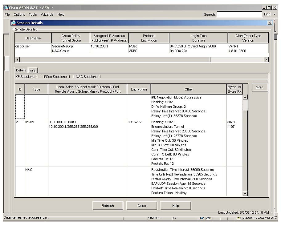
If you would rather get detailed information about a particular EAPoUDP session, you can use the show vpn-sessiondb detail index command followed by an index number to see a detailed connection of the host you are interested in. Example 7-42 shows the output of show vpn-sessiondb detail index 1 to get detailed connection information about ciscouser. The index number is a local ID assigned to the user. Using this command, the security appliance can provide information about the EAPoUDP timers. The security appliance indicates that after 34,567 seconds, it will initiate EAPoUDP revalidation for this host. It also displays a Healthy system posture token associated for that host.
Example 7-42 Displaying EOU Session Details for a Specific Host
CiscoASA# show vpn-sessiondb detail index 1Session Type: Remote DetailedUsername : ciscouserIndex : 1
Using ASDM, you can view the similar NAC session timers by navigating to Monitoring > VPN > VPN Statistics > Sessions and selecting the Details icon. Figure 7-8 illustrates this.
NAC Session Timers in ASDM
You can view a summary of all the VPN and NAC sessions on a security appliance by using the show vpn-sessiondb summary command. As shown in Example 7-43, it displays an active IPSec remote-access session. This session is an active accepted NAC session. Additionally, the security appliance displays cumulative NAC accepted and rejected sessions. This command is useful if you want to determine whether the RADIUS server is successfully assigning the appropriate posture token to the VPN client.
Example 7-43 Displaying Active VPN and NAC Sessions
CiscoASA# show vpn-sessiondb summaryActive Sessions: Session Information: IPSec LAN-to-LAN : 0 Peak Concurrent : 1 IPSec Remote Access : 1 IPSec Limit : 750 WebVPN : 0 WebVPN Limit : 2 SSL VPN Client (SVC) : 0 Cumulative Sessions : 8 Email Proxy : 0 Total Active Sessions : 1 Percent Session Load : 0% VPN LB Mgmt Sessions : 0Active NAC Sessions: Cumulative NAC Sessions: Accepted : 1 Accepted : 14 Rejected : 0 Rejected : 1 Exempted : 0 Exempted : 0 Non-responsive : 0 Non-responsive : 14 Hold-off : 0 Hold-off : 1 N/A : 0 N/A : 0
Summary
The NAC implementation on the Cisco security appliances provides a complete solution to check the posture state of a VPN client. If the posture cannot be validated, the security appliance applies appropriate ACLs to filter traffic. This chapter discussed the packet flow in a security appliance when NAC is enabled and then provided detailed configuration steps. This chapter provided guidance on how to monitor the remote-access VPN tunnels. For troubleshooting purposes, this chapter discussed various debug and log messages to help you isolate the issues related to remote-access tunnels and NAC.
Review Questions
You can find the answers to the review questions in Appendix A, “Answers to Review Questions.”
The default value for the revalidation timer on a security appliance is ________.
1,800 seconds
18,000 seconds
180,000 seconds
None of the above
NAC exception polices can be set up under which of the following locations? (Multiple answers)
Default group policies
User group policies
User policies
Tunnel policies
True or false: A VPN tunnel is considered clientless if it does not report any software version information.
True or false: The NAC exception policies are configured under the tunnel group subconfiguration mode.
True or false: The NAC session’s database cannot be statefully replicated to a standby appliance.
Mode-config attributes are configured under________.
User policy
Default user-group
User group-policy
All of the above
True or false: Specifying a RADIUS server under tunnel-group is a mandatory step.
True or false: The IPSec tunnel is torn down if the VPN client does not respond to an EAPoUDP request packet.
True or false: The NAC exemption list must be applied on a per-group basis.
True or false: Clientless authentication is used for machines that do not have CTA installed.
Copyright © 2007 Pearson Education. All rights reserved.