Cisco Press
You will learn how to configure content switching for the following security protocols in this chapter:
Secure Sockets Layer (SSL) Termination—You can configure your content switch to terminate SSL connections on behalf of clients.
Firewall Load Balancing (FWLB)—You can configure your content switch to distribute client traffic across multiple firewalls.
Virtual Private Network (VPN) Load Balancing (FWLB)—You can configure your content switch to distribute client traffic across multiple VPN concentrators.
SYN-Cookies for SYN-Flood Protection—You will learn how the CSM uses SYN-cookies to prevent SYN-flood attacks from flooding the CSM’s connection table.
In Chapter 10, “Exploring Server Load Balancing,” you learned how to configure content switching to accelerate your applications through the use of server load balancing. In this chapter, you’ll learn four popular ways to accelerate secure content delivery by using content switching:
SSL Termination—You learned about the operation of the SSL protocol in Chapter 8, “Exploring the Application Layer.” Here, you will learn how content switches can off-load SSL computations from your origin servers to dedicated SSL devices and modules.
Firewall Load Balancing—As you learned in Chapter 4, “Exploring Security Technologies and Network Infrastructure Designs,” firewalls provide stateful packet inspection and maintain the context within and across TCP and UDP connections. In this chapter, you will learn how to load balance your traffic across multiple stateful firewalls.
VPN Load Balancing—VPN devices can provide site-to-site or remote access for your corporate users. Content switches can also provide load balancing across multiple VPN concentrators.
SYN-Flood Protection—The Content Switching Module (CSM) uses SYN-cookies to prevent SYN-floods from flooding its connection table.
SSL Termination
With SSL termination, a dedicated SSL termination device terminates the SSL connection, offloading CPU-intensive SSL computations from your origin servers. SSL termination devices have special hardware that can perform the SSL operations.
SSL termination also enables the content switch to parse cleartext application headers to intelligently load balance SSL requests. To provide SSL offloading, you can configure your content switch and SSL termination device to decrypt SSL traffic and forward the cleartext traffic to non-SSL real servers, as Figure 11-1 illustrates.
Figure 11-1
SSL Offloading
Because the content switch sees the request in cleartext, you can configure Layers 5–7 load balancing with SSL termination. Also, because the SSL module forwards traffic in cleartext to real servers, you should make sure that you secure your server farm switches to prevent sniffing of the cleartext traffic.
Note – To encrypt traffic from your SSL termination device to your back-end real servers, you can configure Back-End Encryption on your Content Services Switch (CSS) and CSM. Refer to your product documentation on Cisco.com for more information on Back-End Encryption.
Based on Figure 11-1, a client’s SSL transaction flows through the content network as follows:
The client generates a TCP SYN segment to initiate a TCP connection to the SSL port (443) on the content switch. The content switch receives the TCP segment, issues an HTTPS virtual server lookup, and opens the TCP connection with the client. The client generates a cleartext SSL Client Hello packet and forwards it to the content switch.
Note – Refer to Figure 8-11 in Chapter 8 for more information on the SSL four-way handshake.
The content switch receives the SSL Client Hello and load balances the request to an available SSL termination device. If you configure SSL-sticky on the content switch, the content switch stores the Session ID associated with the connection. The SSL termination device then processes the Client Hello and completes the SSL four-way handshake with the client to establish an encrypted transport session.
Note – If you have multiple SSL devices, you should configure SSL-sticky to ensure that each connection from within the SSL session is load-balanced to the same SSL device. This would be beneficial for clients who want to resume idle SSL sessions, as you learned previously from Figure 8-12 in Chapter 8.
The client generates an HTTPS application request and forwards it to the content switch over the encrypted SSL transport session. The content switch in turn forwards the encrypted request to the appropriate SSL termination device, based on the entry for the existing TCP connection in the content switch’s connection table.
The SSL termination device receives the encrypted application request.
The SSL termination device decrypts the application request, optionally rewrites the URL or any HTTP headers in the request, and forwards it back to the content switch.
Note – You will learn about URL and HTTP Header rewriting later in this chapter.
The content switch receives the cleartext application request, issues an HTTP virtual server lookup, stores any cleartext sticky information (for example, HTTP cookies and source IP addresses) that you configure, and load balances the request to an available real server. The content switch also performs destination Network Address Translation (NAT) on the packet to the real server IP address.
The real server processes the cleartext request and sends the HTTP 200 OK cleartext response to the content switch.
The content switch receives the HTTP 200 OK cleartext response and forwards it to the SSL termination device, based on the connection information in the content switch’s connection table, thus overriding normal TCP/IP routing to the client source IP address. The content switch also reverses the destination NAT performed in Step 6.
The SSL termination device encrypts the response and forwards it to the content switch, again preserving the source and destination IP addresses.
The content switch routes the encrypted SSL packet to the client.
To configure SSL Termination, you can use either:
CSS with an SSL Module—Recall from Chapter 10 that you can install an SSL encryption module in the CSS 11503 or 11506 or obtain a CSS 11501 with an embedded SSL module.
CSM with SSL Daughter Card Module (CSM-S)—You can also obtain a CSM-S for terminating SSL connections. The daughter card module is not field upgradeable—you cannot purchase the daughter card separately for an existing CSM installation.
Configuring Your CSS for SSL Termination
To configure your CSS to offload your SSL connections to an SSL termination device, you must first load your keys and certificates to the SSL termination device. If you are already using public-key infrastructure (PKI) on your real servers and want to upgrade your system with SSL termination, you can import your existing private keys and server certificates to the SSL termination device. Otherwise, you can generate private/public key pairs and Certificate Signing Requests on the SSL termination device and request a server certificate from a Certificate Authority (CA). Once you enroll with a CA and receive the server certificate, you can import the server certificate to your SSL termination device.
Note – You can also use your own private CA to enroll certificates with Cisco CSSs and CSMs. For more information on configuring automatic certificate enrollment with private CAs, see your product documentation on Cisco.com.
Creating and Importing Keys and Certificates on the CSS
You learned about the SSL module that is available for the CSS in Chapter 10. To import pre-existing keys and certificates to your CSS SSL module, you can use the command:
copy ssl [protocol] ftp_record [import filename [format] "password" {"passphrase"}
The passphrase is the existing phrase created with the certificate for encrypting/decrypting. This phrase must be used anywhere you use the certificate, not just on the CSS. You must also create a new password as a second layer of security that the CSS will use to encrypt the imported certificate. This password is local to the CSS and prevents unauthorized administrators from accessing the certificate on the CSS. Before issuing this command, you should first create an FTP record where your certificate and private key is located. You can use the ftp-record command to create a record called import-ssl. You must include your FTP username, your password to the FTP server, and the home directory where the certificate and private key is located on the server. For example:
ftp-record import-ssl 10.1.1.1 cisco "cisco123" /home/sdaros
You can use the following copy ssl command to import a PEM file containing an existing server certificate and private key, called sitecert.pem and sitekey.pem, respectively:
copy ssl sftp import-ssl import sitecert.pem PEM "sanfran" "sanfran"
copy ssl sftp import-ssl import sitekey.pem PEM "sanfran" "sanfran"
You must indicate to the CSS whether the imported files contain a private key or a certificate by using the ssl associate commands:
ssl associate cert mycontentcert sitecert.pem
ssl associate rsakey mycontentkey sitekey.pem
Note – Make sure that you import your CA’s root certificate. Additionally, if your CA issues you a chained certificate, make sure you also import any intermediary certificates within the chain.
Instead of importing existing keys, you can generate an Rivest, Shamir, and Adelman (RSA) public/private key pair for asymmetric encryption on the CSS using the following command:
ssl genrsa filename numbits "password"
This command stores both the private and public key in a single file that you must associate with a certificate name. For example, to generate a key called mycontentkey, use the following commands:
ssl genrsa mycontentkeyfile 1024 "sanfran"
ssl associate rsakey mycontentkey mycontentkeyfile
To generate a CSR for the key pair, use the following command in Example 11-1.
Example 11-1 Generating a CSR on the CSS
(config)# ssl gencsr mycontentkey
You are about to be asked to enter information
that will be incorporated into your certificate
request. What you are about to enter is what is
called a Distinguished Name or a DN.
For some fields there will be a default value,
If you enter '.', the field will be left blank.
Country Name (2 letter code) [US]US
State or Province (full name) [SomeState]California
Locality Name (city) [SomeCity]San Jose
Organization Name (company name) [Acme Inc]Cisco Systems, Inc.
Organizational Unit Name (section) [Web Administration]Network Engineering
Common Name (your domain name) [http://www.acme.com]http://www.cisco.com
Email address [webadmin@acme.com]admin@cisco.com

-----BEGIN NEW CERTIFICATE REQUEST-----
MIctCMtmZONOY+ybEHl/mX0RdqXFnivLBgNVBAYTAlVTMRAwDgYDVQQIEwdHZW9y
DQ kW6Pa6mbjeUV1wffn2dtbKsmz7DnK2BVbml2ZXJzaXR5IG9 yRPs36ywGwDK3
aWExNTAzBgNVBAsTLFVuaXZlcnNpdHkgQ29tcHV0aW5nIGFuZCBOZXR3b3JraW5n
IFNlcnZpY2VzMRYwFAYDVQQDEw13d3ctcy51Z2EuZWR1MIGdMA0GCSqGSIb3DQEB
AQUAA4GLADCBhwKBgQDh3yRPs36ywGwDK3ZS3qaOoNraOFHkSNTsielHUMHxV1/G
N1E43/bifEQJUvSw/nrkOQf3Ync8O/39lelUTJeP6QZkX9Hg1XtuSUov3ExzT53l
vbctCMtmZONOY+ybEHl/mX0RdqXFnivLpXohr7dJ5A1qHfjww/SLW8J/7UXj1QIB
A6AAMA0GCSqGSIb3DQEBBAUAA4GBAIEu35zoGmODCcwwNrTqZk3JQAjyONJxjjtd
uQ+QLQcckO4aghBpcqsgLckW6Pa6mbjeUV1wffn2dtbKsmz7DnK2fwnyaBtxXMvi
CC4o9uvW11i5TjdorfOdRI1lR0FrNAzf+3GQUl1S2a83wagvFjo12yUCukrxBgyU
bXbmNuJpkdsjdkjfkdjfkdfjdkfjdkfjdkfj
-----END NEW CERTIFICATE REQUEST-----
To apply for a server certificate, you must send the CSR to a CA of your choice. Most well-known CAs allow you to cut and paste your CSR to their websites and will issue you a server certificate via e-mail within a few business days. Once you receive your server certificate (called sitecert.pem in this example), you can import it using the copy ssl command that you learned previously:
copy ssl sftp import-ssl import sitecert.pem PEM "sanfran" "sanfran"
ssl associate cert mycontentcert sitecert.pem
Note – Make sure you keep track of when your certificates expire. You will need to obtain new certificates before they expire. Otherwise, clients will receive an error when they attempt to download the expired certificate.
Terminating SSL on the CSS
Now that you have a server certificate and a private key on your CSS, you can configure your CSS to terminate SSL connections on behalf of your real servers, as illustrated in Example 11-2.
Note – Note that there is no IP addressing and server destination-Network Address Translationing (DNATing) involved when configuring the CSS SSL module.
Example 11-2 Configuring Your CSS to Terminate SSL Connections
ssl-proxy-list ssl_proxy
 ssl-server 1
 ssl-server 1 vip address 10.1.10.1
 ssl-server 1 port 443
 ssl-server 1 rsacert mycontentcert
 ssl-server 1 rsakey mycontentkey
 ssl-server 1 cipher TLS_RSA_WITH_RC4_128_MD5 10.1.10.100 80 weight 5
 ssl-server 1 cipher TLS_RSA_WITH_RC4_128_SHA 10.1.10.100 80 weight 10
 ssl-server 1 http-header session
 ssl-server 1 urlrewrite 1 http://www.cisco.com
 active

service ssl-serv1
 type ssl-accel
 add ssl-proxy-list ssl_proxy
 slot 5
 keepalive type none
 active

service ssl-serv2
 type ssl-accel
 add ssl-proxy-list ssl_proxy
 slot 6
 keepalive type none
 active

service web01
 ip address 10.1.10.10
 active

service web02
 ip address 10.1.10.11
 active

owner cisco
 content https-vip
 vip address 10.1.10.100
 protocol tcp
 port 443
 add service ssl-serv1
 add service ssl-serv2
 active

content http-vip
 vip address 10.1.10.100
 protocol tcp
 port 80
 add service web01
 add service web02
 active
Configuring URL and Header Rewrite on the CSS
You learned previously that, without back-end encryption, real servers receive cleartext requests and send HTML page responses in cleartext (in Steps 6–8 from Figure 11-1). However, if an HTML page includes embedded HTML references to other sites, you need to make sure that these links are prefixed by “https://” and not “http://”; otherwise, your browser may give you an error while accessing the secure site.
For example, your HTML page may include the following links:
To inform your HTTP server that the current cleartext request is from the CSS SSL module (in Step 6) and is not a client request, you can configure the CSS SSL module to add an HTTP header to the HTTP request. For example, you can add an HTTP header including the SSL session information. To enable the CSS to insert SSL session information HTTP headers into requests that it proxies, use the following proxy list mode command, as Example 11-2 illustrates:
ssl-server number http-header session
You can then configure your HTTP servers to recognize these headers and supply an HTML page containing “https://” within the embedded links instead of “https://.”
Note – You can also configure the CSS to insert the client and server certificates as HTTP headers using the client-cert and server-cert keywords of the ssl-server http-header proxy list command.
Additionally, if your servers send HTTP 300 series redirects to your clients, then you should configure your CSS to rewrite the “http://” reference in the “Location:” header of HTTP 300 series redirect methods to “https://” with the proxy list command:
ssl-server number urlrewrite number hostname [sslport port {clearport port}]
This command enables you to specify particular URLs that you want to rewrite in HTTP 300 series redirects, by including the exact URL or by using wildcards. Entries without wildcards take precedence over wildcard entries, and prefix wildcards entries take precedence over suffix wildcard entries. For example, you can configure your CSS to rewrite all redirects for “*.cisco.com” (prefix wildcard) and “http://www.cisco.*” (suffix wildcard) with the commands:
ssl-server 1 urlrewrite 1 *.cisco.com
ssl-server 1 urlrewrite 1 http://www.cisco.*
You can also rewrite nonstandard cleartext HTTP ports (that is, any port other than port 80) with either the standard SSL port (that is, port 443) or nonstandard SSL ports. For example, the following command will rewrite “http://www.cisco.com:81” to “https://http://www.cisco.com”:
ssl-server 1 urlrewrite 1 http://www.cisco.com clearport 81
The following command rewrites “http://www.cisco.com” to “https://http://www.cisco.com:444”:
ssl-server 1 urlrewrite 1 http://www.cisco.com sslport 444
The following command rewrites “http://www.cisco.com:81” to “https://http://www.cisco.com:444”:
ssl-server 1 urlrewrite 1 http://www.cisco.com sslport 444 clearport 81
Note – Neither the CSM nor CSS supports rewriting HTTP URLs embedded directly within HTML pages.
Configuring Your Content Services Module with SSL
You can also configure your CSM-S for SSL termination. As with the CSS with an SSL module, you can import existing keys and server certificates to your CSM-S daughter card or generate new keys and request server certificates from a CA.
Note – You can also configure SSL termination with the CSM using a separate SSL services module (SSLM). The configuration for the SSLM is the same as the CSM-S. For more information on the SSLM, refer to its product documentation on Cisco.com.
Creating and Importing Keys and Certificates on the CSM
To generate a private/public key pair on your CSM-S daughter card, use the command:
crypto key generate rsa general-keys label key-label [exportable] [modulus size]
For example, the crypto key generate command produces the output in Example 11-3 to generate a key pair called mycontentkey on the CSM-S. If you want to be able to export the private key from the SSL daughter card for future use outside the CSM-S, you can use the exportable keyword.
Example 11-3 Configuring Your CSM to Generate an RSA Key Pair
ssl-card(config)# crypto key generate rsa general-keys label mycontentkey exportable
The name for the keys will be: mycontentkey
Choose the size of the key modulus in the range of 360 to 2048 for your
General Purpose Keys. Choosing a key modulus greater than 512 may take
a few minutes.

How many bits in the modulus [512]: 1024
Generating RSA keys.... [OK].
To enter your organization’s information for a CSR, you must create a trust point, as Example 11-4 illustrates.
Example 11-4 Configuring a Trust Point on the CSM-S
crypto ca trustpoint mycontent-trustpoint
 rsakeypair mycontentkey
 serial
 subject-name C=US, ST=California, CN=http://www.cisco.com, OU=Network Engineering, O=Cisco Systems, Inc.
 enrollment url tftp://10.1.1.1/certificates
To generate a CSR for the key pair, use the command:
crypto ca enroll trustpoint-name
For example, Example 11-5 shows the command output to generate a request for the key pair mycontentkey that Example 11-3 previously generated.
Example 11-5 Creating a CSR on Your CSM-S
ssl-card(config)# crypto ca enroll mycontent-trustpoint
% Start certificate enrollment ..

% The subject name in the certificate will be:CN=http://www.cisco.com, OU=Network Engineering, O=Cisco Systems, Inc.
% The fully-qualified domain name in the certificate will be:http://www.cisco.com
% The subject name in the certificate will be:http://www.cisco.com
% The serial number in the certificate will be:B0FFF22E
% Include an IP address in the subject name? [no]:no
Display Certificate Request to terminal? [yes/no]:yes
Certificate Request follows:

MIctCMtmZONOY+ybEHl/mX0RdqXFnivLBgNVBAYTAlVTMRAwDgYDVQQIEwdHZW9y
DQ kW6Pa6mbjeUV1wffn2dtbKsmz7DnK2BVbml2ZXJzaXR5IG9 yRPs36ywGwDK3
aWExNTAzBgNVBAsTLFVuaXZlcnNpdHkgQ29tcHV0aW5nIGFuZCBOZXR3b3JraW5n
IFNlcnZpY2VzMRYwFAYDVQQDEw13d3ctcy51Z2EuZWR1MIGdMA0GCSqGSIb3DQEB
AQUAA4GLADCBhwKBgQDh3yRPs36ywGwDK3ZS3qaOoNraOFHkSNTsielHUMHxV1/G
N1E43/bifEQJUvSw/nrkOQf3Ync8O/39lelUTJeP6QZkX9Hg1XtuSUov3ExzT53l
vbctCMtmZONOY+ybEHl/mX0RdqXFnivLpXohr7dJ5A1qHfjww/SLW8J/7UXj1QIB
A6AAMA0GCSqGSIb3DQEBBAUAA4GBAIEu35zoGmODCcwwNrTqZk3JQAjyONJxjjtd
uQ+QLQcckO4aghBpcqsgLckW6Pa6mbjeUV1wffn2dtbKsmz7DnK2fwnyaBtxXMvi
CC4o9uvW11i5TjdorfOdRI1lR0FrNAzf+3GQUl1S2a83wagvFjo12yUCukrxBgyU
bXbmNuJpkdsjdkjfkdjfkdfjdkfjdkfjdkfj

---End - This line not part of the certificate request---

Redisplay enrollment request? [yes/no]:no
As you learned previously, to apply for a server certificate, you must send the CSR to a public CA of your choice (such as Verisign), or to your own private CA (such as Microsoft Certificate Services). If you use a public CA, once you receive the server certificate, you can TFTP it to the CSM-S using the crypto ca import command, as Example 11-6 illustrates. The CSM-S connects to the TFTP server specified previously in Example 11-4 using the enrollment url command. Make sure your certificate exists on a valid TFTP server before using the crypto ca import command.
Alternately, if you use a private CA, you can specify its URL with the enrollment url command, and the crypto ca import command will connect to the private CA to download the server certificate.
Example 11-6 Importing a Server Certificate on Your CSM-S
ssl-card(config)# crypto ca import mycontent-trustpoint certificate
% The fully-qualified domain name in the certificate will be: ssl-card.cisco.com
Retrieve Certificate from tftp server? [yes/no]:yes
% Request to retrieve Certificate queued

ssl-proxy(config)#
Loading mycontent-trustpoint.crt from 10.1.1.1 (via Ethernet0/0.172):!
[OK - 1608 bytes]

ssl-proxy(config)#
*Nov 25 21:52:36.299:%CRYPTO-6-CERTRET:Certificate received from Certificate Authority
ssl-proxy(config)# ^Z
Note – Make sure you load your CA’s certificate (and intermediate certificate, if necessary) to the CSM-S using the crypto ca authenticate command. Also use the enrollment url command to make sure that the CA’s certificate resides on the TFTP server you specify. If you are using your own private CA, the crypto ca authenticate command will load the CA certificate from the private CA.
Alternately, if you have existing private keys and certificates, you can import them into your SSL daughter card. For example, to import an existing PKCS#12 key, you need to have previously generated the PKCS#12 file using an external PKI system. Recall from Chapter 8 that a PKCS#12 file can contain a private key and server certificate chain.
Then, to import the existing private key and server certificate chain from the PKCS#12 file to your CSM-S, you can use the following command:
crypto ca import trustpoint_label pkcs12 {scp: | ftp: | nvram: | rcp: | tftp:} [pkcs12_filename] pass_phrase
Note – Using the crypt ca import command to import PKCS#12 certificates automatically generates the trust point configuration for use in your SSL proxy services. You will learn how to configure a proxy service on the SSL daughter card later in this section.
Terminating SSL on the CSM-S
Now that you have private keys and server certificates on your SSL daughter card, you can configure your CSM-S to terminate SSL connections. You can configure the content switch either in NAT-mode (that is, the content switch will destination-NAT the client’s request to the SSL daughter card’s IP address in Step 2 from Figure 11-1) or in dispatch mode (that is, the content switch will route the packet directly to the SSL daughter card without DNATing it). If you configure the content switch in NAT-mode, make sure you configure the SSL daughter card to DNAT the packet back to the virtual server IP address. Example 11-7 shows how to configure your CSM to terminate SSL connections in dispatch-mode, based on the network topology in Figure 11-2. For the example in this section, the SSL daughter card farm is in bridge-mode and the real server farm is in router-mode, as Figure 11-2 illustrates.
Figure 11-2
Dispatch-Mode CSM with SSL Daughter Card in Bridge-Mode
Example 11-7 Configuring Your CSM to Terminate SSL in Bridge-Mode
interface vlan 10
 description *** Client VLAN
 ip address 10.1.10.2


interface fastethernet 2/1
 description *** Web01
 switchport vlan 30

interface fastethernet 2/2
 description *** Web02
 switchport vlan 30

ip route 10.1.30.0 255.255.255.0 10.1.10.1
ip route 10.1.99.0 255.255.255.0 10.1.10.1
module csm 5

vlan 10 client
 ip address 10.1.10.1 255.255.255.0
 gateway 10.1.10.2

 vlan 20 server
 ip address 10.1.10.1 255.255.255.0

vlan 30 server
 ip address 10.1.30.1 255.255.255.0

vlan 99 server
 ip address 10.1.99.1 255.255.255.0

serverfarm ssl-accel-farm
 no nat server
 no nat client
 real 10.1.10.10 local
 inservice

serverfarm webfarm
 nat server
 no nat client
 real 10.1.30.10
 inservice
 real 10.1.30.11
 inservice

serverfarm forward-route
 no nat server
 no nat client
 predictor forward

vserver https-vip
 virtual 10.1.10.100 tcp https
 vlan 10
 serverfarm ssl-accel-farm
inservice

vserver http-vip
 virtual 10.1.10.100 tcp www
 serverfarm webfarm
 persistent rebalance
 inservice

vserver direct-web
 virtual 10.1.30.0 255.255.255.0 any
 serverfarm forward-route
 inservice

vserver direct-ssl
 virtual 10.1.99.0 255.255.255.0 any
 serverfarm forward-route
 inservice
Here are some notes to help you understand the configuration in Example 11-7.
Recall from Chapter 10 that configuring bridge-mode requires that you give the client VLAN 10 and server VLAN 20 interfaces the same IP address (that is, 10.1.10.1 in Example 11-7).
Use the no nat server command to prevent the CSM from DNATing client requests to the SSL daughter card (thus enabling dispatch-mode processing).
The virtual server “http-vip” serves traffic from both cleartext client requests and from unencrypted traffic forwarded by the SSL daughter card.
The command vlan 10 within the “https-vip” virtual server configuration indicates that the virtual server shall receive traffic from only VLAN 10.
You need to include the local keyword when configuring the SSL daughter card as a real server within a server farm. This keyword indicates to the CSM that the real server is the SSL daughter card and not an external real server.
The “direct-type” virtual server is necessary for you to be able to directly connect to your secure router-mode real servers for testing purposes. You also need to add a static route to the MSFC pointing to the CSM client IP address for the subnet of the router-mode reals (for example, ip route 10.1.30.0 255.255.255.0 10.1.10.1, in Example 11-7).
VLAN 99 is for administering the SSL daughter card using Telnet.
Because the SSL devices preserve the source IP address of the packet as the client’s IP address, the CSM-S must use special routing for real-server return traffic. If the CSM-S uses normal routing, the cleartext real server return packets are routed to the client directly, bypassing the SSL daughter card. Therefore, the CSM-S routes the back-end real server return packets to the SSL daughter card by tracking the Layer 2 MAC address of the SSL daughter card during the connection flow.
Example 11-8 gives the corresponding SSL daughter card configuration for CSM-S termination. Whereas with the CSM-S you did not have to directly configure the SSL module with IP addressing, you must configure the CSM-S daughter card with an IP address and default gateway. The SSL daughter card is a separate TCP/IP host on the network and, as such, it responds to ARP requests. You must also administer it separately via Telnet through a separate command line interface.
Example 11-8 Configuring Your SSL Daughter Card for SSL Termination
ssl-proxy vlan 99
 ipaddr 10.1.99.3 255.255.255.0
 gateway 10.1.99.1
 admin

ssl-proxy vlan 20
 ipaddr 10.1.10.10 255.255.255.0
 gateway 10.1.10.1

ssl-proxy service ssl-termination
 virtual ipaddr 10.1.10.100 protocol tcp port 443 secondary
 server ipaddr 10.1.10.1 protocol tcp port 80
 no nat server
 certificate rsa mycontent-trustpoint certs-key
 inservice
Here are some notes to help you understand the configuration in Example 11-8.
The ssl-proxy service command creates the virtual server called “ssl-termination.” Virtual servers on the daughter card function in the same manner as on content switches. You must assign the same IP address and port to the virtual server. When the SSL proxy receives packets that match the virtual server, it decrypts the packets and sends them to the configured real server using the server command, which is simply its default gateway (that is, the CSM-S IP address 10.1.10.1). If there were multiple CSM-Ss, you would add them using the server command.
Because this is a dispatch-mode configuration, you should disable server DNAT on the SSL daughter card using the no nat server command; otherwise, the request will be DNATed from the VIP to the IP address of the CSM.
Specify the RSA certificate that you want to assign to the service by using the certificate rsa command. This example uses the certificate “mycontent-trustpoint” imported in Example 11-6.
Because the SSL daughter card is in bridge-mode and is configured with the same virtual IP as the CSM-S, it receives the same ARP requests from the MSFC that the CSM-S receives. The secondary keyword prevents the SSL daughter card from responding to these ARP requests.
Configuring URL and Header Rewrite on the CSM
To enable the SSL daughter card to insert HTTP headers to inform the server that the SSL daughter card is proxying the connection, you can create an HTTP header policy on the SSL daughter card. Example 11-9 illustrates how to create an HTTP header policy and assign it to an SSL proxy service.
Example 11-9 Creating an HTTP Header Policy
ssl-proxy policy http-header insert-session-info
 session

ssl-proxy service ssl-termination
 virtual ipaddr 10.1.10.100 protocol tcp port 443 secondary
 server ipaddr 10.1.10.1 protocol tcp port 80
 no nat server
 certificate rsa mycontent-trustpoint certs-key
 policy http-header insert-session-info
 inservice
Similar to the CSS SSL daughter card, if your servers send HTTP 300 series redirects to your clients, then you should configure your CSM-S to rewrite the “http://” reference in the “Location:” header. To inspect the “Location:” header and replace “http://” with “https://” on the SSL daughter card, you can use the configuration in Example 11-10.
Example 11-10 Creating an HTTP URL Rewrite Policy
ssl-proxy policy url-rewrite rewrite-redirects
 url *.cisco.com
 url http://www.cisco.*
 url http://www.cisco.com sslport 444
 url http://www.cisco.com sslport 444 clearport 81

ssl-proxy service ssl-termination
 virtual ipaddr 10.1.10.100 protocol tcp port 443 secondary
 server ipaddr 10.1.10.1 protocol tcp port 80
 no nat server
 certificate rsa mycontent-trustpoint certs-key
 policy url-rewrite rewrite-redirects
 inservice
Firewall Load Balancing
Firewalls can realize performance benefits from Cisco content switching by using Firewall Load Balancing (FWLB) technologies. Although most firewalls can be scaled inherently by supporting stateful failover to a standby unit, you can increase performance by load balancing requests across multiple active firewalls using the CSS or CSM.
CSS Firewall Load Balancing
To control traffic flowing in both directions across a group of firewalls, you must sandwich the group within two CSSs. The CSSs distribute requests over the firewalls and maintain the connection state flowing through the firewalls. The content switches use the state to intelligently switch packets from existing connections to the same firewall. Figure 11-3 illustrates how you can sandwich your firewalls between two CSSs.
Figure 11-3
CSS Firewall Load Balancing
Note – You can provide CSS redundancy by installing two CSSs on both the inside and outside of the firewall group and configure the highly available features that you learned about in Chapter 10. This way you avoid having two single points of failure with the CSSs that are shown in Figure 11-3.
In Figure 11-3, consider an incoming TCP SYN segment from the Internet:
The CSS A decides which firewall to switch the request to, based on the configured SLB policy (for example, round-robin or hashing the source and destination IP addresses).
CSS A creates a connection entry for the request in its state table.
The selected firewall processes the request, creates a connection entry in its connection table, and forwards the TCP SYN segment to the CSS B.
CSS B simply forwards the packet to the destination: If the destination is a virtual server, the request is load-balanced to the server according to the rules specified for the server farm; otherwise, the packet is routed using the content switch’s routing table.
CSS B also creates a connection entry in its connection table.
The server processes the request and sends a TCP SYN-ACK response back to CSS B.
CSS B looks up the connection in its connection table based on the information in the IP and TCP headers in the response, and updates the connection state with the SYN-ACK.
CSS B forwards the packet to the appropriate firewall based on the existing entry in its connection table.
The firewall updates its state with the SYN-ACK packet and forwards it to CSS A.
CSS A routes the request to the Internet per normal routing and updates its connection state.
The client’s ACK then completes the TCP full-handshake over the same path as the original SYN segment.
Configuring FWLB differs slightly from configuring standard server load balancing (SLB) because the traffic is not destined to the firewall, but to services behind the firewall. To configure firewalls on the CSS, use the command:
ip firewall index local_firewall_address remote_firewall_address remote_switch_address
You must configure the same index values on both CSSs. To add routes to back-end servers that you want to load balance across your firewalls, use the command:
ip route ip_address subnet_mask firewall index distance
Example 11-11 gives a sample FWLB configuration based on the topology in Figure 11-3.
Example 11-11 CSS FWLB
CSS A
ip firewall 1 10.1.10.2 10.1.20.2 10.1.20.1
ip route 10.1.30.0/24 firewall 1

ip firewall 2 10.1.10.3 10.1.20.3 10.1.20.1
ip route 10.1.30.0/24 firewall 2

interface e1
 bridge vlan 10

interface e2
 bridge vlan 10

circuit vlan 10
 ip address 10.1.10.1 255.255.255.0
CSS B
ip firewall 1 10.1.20.2 10.1.10.2 10.1.10.1
ip route 0.0.0.0/0 firewall 1

ip firewall 2 10.1.20.3 10.1.10.3 10.1.10.1
ip route 0.0.0.0/0 firewall 2

interface e1
 bridge vlan 20

interface e2
 bridge vlan 20

interface e3
 bridge vlan 30

circuit vlan 20
 ip address 10.1.20.1 255.255.255.0

circuit vlan 30
 ip address 10.1.30.1 255.255.255.0
Note – Firewalls have drastically improved in performance over the past few years. The content switch must be at least X times more powerful than the firewalls being balanced, where X is the number of firewalls being balanced. Although the CSS supports FWLB, the CSM is preferable for FWLB for new deployments because its performance is better than the CSS in terms of bandwidth and flow-handling capabilities. Also, the CSS does not support reverse sticky for Active-FTP, as you will learn in the next section.
CSM Firewall Load Balancing
As you will quickly learn, with the CSM in router-mode, virtual servers are required for any traffic to pass through it. As a result, the configurations are generally more complicated than those of the CSS, but can be much more flexible. For example, the CSM enables you to configure complex designs, including single-CSM FWLB and stealth-firewall load balancing, which are not possible with the CSS.
Figure 11-4 gives a basic dual-CSM FWLB topology.
Figure 11-4
Dual-CSM FWLB
To achieve the FWLB design in Figure 11-4, you can use the configuration in Example 11-12.
Example 11-12 Dual-CSM FWLB
! MSFC shared by both CSMs
interface vlan 10
 ip address 10.1.10.4 255.255.255.0
 no shutdown
! CSM A
mod csm 5
vlan 10 client
 ip address 10.1.10.1 255.255.255.0
 gateway 10.1.10.4

vlan 11 server
 ip address 10.1.10.1 255.255.255.0

serverfarm forward
 description ** Used to forward outgoing connections from the web servers **
 no nat server
 no nat client
 predictor forward

serverfarm out-firewalls
 description ** Contains the outside interfaces of the firewalls **
 no nat server
 no nat client
 predictor hash address source 255.255.255.255
 real 10.1.10.2
 backup real 10.1.10.3
 inservice
 real 10.1.10.3
 backup real 10.1.10.2
 inservice

vserver in-connections
 description ** Distributes incoming connections from clients across firewalls **
 virtual 10.1.20.0 255.255.255.0 any
 vlan 10
 serverfarm out-firewalls
 inservice

vserver out-connections
 description ** Forwards outgoing connections from the web servers according to routing table **
 virtual 0.0.0.0 0.0.0.0 any
 serverfarm forward
 vlan 11
 inservice
! CSM B
mod csm 6

vlan 20 client
 ip address 10.1.20.1 255.255.255.0

vlan 21 server
 ip address 10.1.20.1 255.255.255.0

serverfarm in-firewalls
 description ** Contains the inside firewall interfaces **
 no nat server
 no nat client
 predictor leastconns
 real 10.1.20.2
 backup real 10.1.20.3
 inservice
 real 10.1.20.3
 backup real 10.1.20.2
 inservice

serverfarm web-farm
 description ** Contains the two web servers **
 nat server
 no nat client
 real 10.1.20.10

 inservice
 real 10.1.20.11
 inservice
vserver out-connections
 description ** Distributes outgoing connections initiated from the web servers across the available firewalls **
 virtual 0.0.0.0 0.0.0.0 any
 vlan 20
 serverfarm in-firewalls
 inservice

vserver web-vip
 description ** Distributes incoming connections initiated from external clients across web servers **
 virtual 10.1.20.100 255.255.255.0 www
 vlan 21
 serverfarm web-farm
 inservice
Note – In Figure 11-4, CSM A and CSM B are installed within the same chassis as the MSFC, in slots five and six, respectively.
When a client initiates a connection from the Internet to the web server virtual IP (VIP) 10.1.20.100 on CSM B, CSM A is the first CSM to receive the packet and performs a virtual server lookup, matching the client’s TCP SYN packet to the VIP called in-connections. This VIP distributes incoming connections from clients across the available firewalls in the server farm “out-firewalls” using the least connections predictor, which will produce even more distribution across your firewalls than source IP hashing. Single-connection TCP protocols, such as SMTP and BGP, require only one TCP connection for the application to work. As a result, you do not require hashing or sticking of subsequent application requests that occur over different TCP connections to the originally selected firewall.
The server farm “out-firewalls” contains the outside IP addresses of the firewalls you are load balancing. For example, say that CSM A selects Firewall B for the new connection. Then, CSM A creates a new connection in its connection table and forwards the packet to Firewall B. Firewall B also creates a new connection in its connection table and forwards the packet to CSM B. CSM B creates a new connection in its connection table and performs a virtual server lookup, matching the virtual server called “web-vip.” CSM B then performs delayed binding with the client and eventually load balances the request to a real web server (for example, Web01). Web01 responds with a TCP SYN-ACK that traverses the same firewall as the original SYN did due to the existing connection entry in CSM B’s connection table.
Note – If your firewalls support stateful failover, you can use the backup real real server configuration command to specify the backup firewall.
When either back-end web server requires the initiation of a connection to the Internet, CSM B first receives the TCP SYN segment (assuming you configure the reals with CSM B as their default gateway), performs a virtual server lookup, and matches its VIP called “out-connections.” This VIP distributes connections initiated from web servers across the available firewalls in the server farm “in-firewalls” using destination IP address hashing. As with using source hashing for incoming requests, you should use destination hashing for outgoing requests to distribute the connections across the firewalls more evenly.
Note – The CSM also supports UDP-based protocols for FWLB.
Similar to “out-firewalls” configured on CSM A, the server farm “in-firewalls” on CSM B contains the inside IP addresses of the firewalls you are load balancing. In this case, say that CSM B chooses Firewall A. Then both CSM B and Firewall A create a connection state entry for the new connection in their connection tables and forward the segment upstream. When CSM A receives the TCP SYN, it matches the segment with the VIP called “out-connections” and forwards the packet to the Internet using its internal routing table, as the server farm “forward” stipulates.
Configuring Reverse Stickiness
Recall the sticky features that you learned in Chapter 10. You can configure stickiness when you require load balancing multiple TCP flows of a session to the same server as the original flow, to retain information stored about the flow on the server. The same principle is true with FWLB. For applications that require multiple connections in the same direction within the same application session, such as HTTP and Passive-FTP, you can use IP session stickiness or distribution via address hashing to ensure that multiple TCP sessions stick to the same firewall. That is, you can apply the same “forward” sticky configuration that you learned in Chapter 10 to FWLB.
However, for applications that open connections in both directions within the same session, such as Active-FTP, you must use IP reverse-sticky to ensure that TCP connections in the reverse direction take the same firewall. In the previous example, CSM A chose Firewall B for the client connection, but CSM B chose Firewall A for the server-initiated connection. With applications such as Active-FTP, you will require CSM B to choose Firewall B so that your firewall can reconcile the FTP data and control “buddy” connections for security purposes. Refer to Figure 11-5 to understand how IP reverse-sticky works.
Figure 11-5
IP Reverse-Sticky
Configuring IP reverse-sticky on CSMB enables it to store a sticky entry in its sticky table during the initial connection made by the client. IP reverse-sticky forces CSMB to override its normal load balancing decision-making process for subsequent connection requests made by the real servers to clients located in its sticky database.
To configure IP reverse-sticky on CSMB, you can use the configuration in Example 11-13, as applicable to the previous HTTP configuration on CSM B; however, HTTP virtual servers do not normally require reverse-sticky—Active-FTP is the most common application to use reverse- sticky.
Example 11-13 IP Reverse-Sticky
sticky 77 netmask 255.255.255.255 address destination timeout 100

vserver out-connections
 virtual 0.0.0.0 0.0.0.0 any
 vlan 20
 serverfarm in-firewalls
 sticky 100 group 77
 inservice

vserver web-vip
 virtual 10.1.20.100 255.255.255.0 www
 vlan 21
 serverfarm web-farm
 reverse-sticky 77
 inservice
In Figure 11-5 you can see that, when the incoming client connection via Firewall B matches the virtual server “web-vip,” CSM B creates a sticky entry with the client’s source IP address (10.1.10.99) and the real server (Firewall B) in the sticky database. Subsequent TCP connections from the back-end real servers trigger CSM B to perform a sticky table lookup on the destination IP address of the request. If a real server initiates a connection to 10.1.10.99, CSM B forwards the TCP SYN request through Firewall B, thus overriding the normal outgoing load-balancing method of destination hashing.
Configuring Single-CSM FWLB
In a single-CSM FWLB configuration, as Figure 11-6 suggests, you must connect the inside and outside interfaces of the firewalls directly to the CSM.
Single-CSM FWLB
Example 11-14 gives a single-CSM FWLB configuration.
Example 11-14 Configuring FWLB with a Single CSM
mod csm 4
 vlan 10 client
 description *** Client's initiate connections from VLAN 10
 ip address 10.1.10.1 255.255.255.0

 vlan 20 server
 description *** VLAN 20 contains the firewalls outside interfaces  ip address 10.1.20.1 255.255.255.0

 vlan 30 server
 description *** VLAN 30 contains the firewalls inside interfaces
 ip address 10.1.30.1 255.255.255.0

 vlan 40 server
 description *** Internal subnet for web servers  ip address 10.1.40.1 255.255.255.0

serverfarm forward
 no nat server
 no nat client
 predictor forward

serverfarm in-firewalls
 description ** Contains the inside interfaces of the firewalls **  no nat server
 no nat client
 predictor hash address source 255.255.255.255
 real 10.1.20.10
 inservice
 real 10.1.20.11
 inservice

serverfarm out-firewalls
description ** Contains the outside interfaces of the firewalls **
 no nat server
 no nat client
 predictor hash address destination 255.255.255.255
 real 10.1.30.10
 inservice
 real 10.1.30.11
 inservice

serverfarm web-farm
 description ** Contains the web servers **
 nat server
 no nat client
 real 10.1.40.10
 inservice
 real 10.1.40.11
 inservice

vserver in-connections
 description ** Distributes incoming connections across the two firewalls **
 virtual 10.1.40.0 255.255.255.0 any
 vlan 10
 serverfarm out-firewalls
 inservice

vserver out-conns-20
 description ** Routes outgoing connections from the web servers from VLAN 20 to the Internet according to the routing table **
 virtual 0.0.0.0 0.0.0.0 any
 serverfarm forward
 vlan 20
 inservice

vserver out-conns-40
 description ** Distributes outgoing connections from the web servers from VLAN 40 across the two firewalls **
 virtual 0.0.0.0 0.0.0.0 any
 vlan 40
 serverfarm in-firewalls
 inservice

vserver web-vip
 description ** Distributes incoming connections from the Internet from VLAN 30 across the two web servers **
 virtual 10.1.40.100 255.255.255.0 www
 vlan 30
 serverfarm web-farm
 inservice
When the CSM receives a client TCP SYN segment from the client VLAN 10 for the VIP 10.1.40.100, it performs a virtual server lookup and matches it to virtual server “in-connections.” The CSM then load balances the request across the two firewalls that are shown in Figure 11-6 and chooses Firewall B. The CSM forwards the request out on VLAN 20, and Firewall B forwards it back on VLAN 30. The CSM receives the request on VLAN 30, performs another virtual server lookup, and matches the virtual server called “web-vip.” The CSM load balances the request to the real—return traffic from the real flows through the same firewall given the existing CSM connection table entry.
Server-originated connections arrive to the CSM from VLAN 40, match the VIP “out-conns-40,” and are load balanced to the firewalls. The firewalls forward the outgoing connection requests back to the CSM on VLAN 20. The CSM matches the VIP “out-conns-20” and forwards the request to the client using its routing table.
Note – To configure stealth-mode FWLB, refer to your product documentation on Cisco.com.
VPN Load Balancing on the CSM
You can load balance VPN connections across the CSM to increase the performance and provide redundancy to your VPN termination devices. Example 11-15 gives a dispatch-mode CSM VPN load balancing configuration.
Example 11-15 Configuring VPN Load Balancing on the CSM
serverfarm vpn-farm
 no nat server
 no nat client
 real 10.1.10.10
  inservice
 real 10.1.10.12
  inservice

 sticky 5 netmask 255.255.255.255 timeout 60

 policy vpn-policy
 sticky-group 5
 serverfarm vpn-farm

vserver vpn-ah
 virtual 10.1.10.100 51
 slb-policy vpn-policy
 inservice

 vserver vpn-esp
 virtual 10.1.10.100 50
 slb-policy vpn-policy
 inservice

vserver vpn-ike
 virtual 10.1.10.100 udp 500
 slb-policy vpn-policy
 inservice
Note – The CSS does not support VPN load balancing because it does not understand the IPSec protocols.
To configure your CSM for VPN load balancing, you must create virtual servers for the Authentication Header (AH), Encrypted Security Payload (ESP), and Internet Key Exchange (IKE) protocols. Similar to SSL, IPsec-based VPNs use multiple TCP connections to establish VPN sessions. Therefore, to ensure that clients stick to the same VPN concentrator across TCP connections, you should configure source IP address stickiness using the sticky netmask command.
Note – If you want to configure directed-mode VPN load balancing, simply enter the command nat server in server farm configuration mode. Be cautious when rewriting fields within VPN traffic on your content switch because many VPN protocols have security features that protect the integrity of VPN messages.
Preventing Connection Table Flooding using SYN-Cookies
To avoid filling up its connection table during SYN-flood-based Denial of Service (DoS) attacks, the CSM uses SYN-cookies, which were covered briefly in Chapter 4. With SYN-flood attacks, the attacker sets random source IP addresses in numerous SYN packets that it sends to its victim. The victim receives the SYN packet, creates an entry in its connection table, responds with a TCP SYN-ACK packet, and awaits the final ACK segment from the sender. The final segment never arrives. Thus, the victim’s connection fills very quickly with incomplete TCP connection entries.
However, with SYN-cookies, instead of allocating a record for every SYN segment from its clients, the CSM sends SYN-ACK segments with carefully constructed sequence numbers generated as a hash of connection’s 4-tuple, the Maximum Segment Size, and a secret that continuously changes as time goes by. The connection 4-tuple contains the source and destination IP addresses and source and destination ports. When valid clients respond to the SYN-ACK with an ACK, they will include this special sequence number, which the CSM can verify before creating the connection entry. Without SYN-cookies, the CSM creates connection entries when it receives the initial SYN packet from clients. With SYN-cookies, the CSM creates the connection when it verifies the client’s ACK segment to complete the connection. Because SYN-flood attackers typically do not respond to SYN-ACK segments, the SYN-flood traffic will not flood the CSM’s connection table. Figure 11-7 illustrates SYN-cookies in practice.
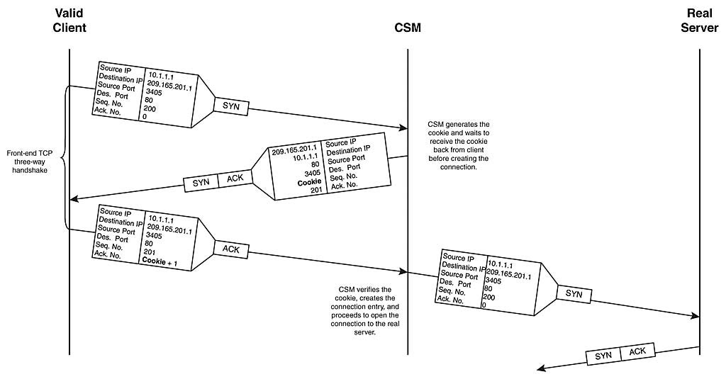
Using SYN-Cookies to Prevent SYN-Flood Traffic from Flooding the CSM Connection Table
Summary
In this chapter, you learned how to configure the following technologies on your content switches:
Secure Sockets Layers (SSL) Termination—You learned how to configure your CSS and CSM to terminate SSL connections on behalf of clients.
Firewall Load Balancing (FWLB)—You learned how to configure your CSS and CSM to distribute client traffic across multiple firewalls.
Virtual Private Network (VPN) Load Balancing (FWLB)—You learned how to configure your CSM to distribute client traffic across multiple VPN concentrators.
SYN-Cookies for SYN-Flood Protection—You learned how the CSM uses SYN-cookies to prevent SYN-flood attacks from flooding the CSM’s connection table.
Content switching enables you to increase the performance of your SSL, firewall, and VPN devices, in terms of packets per second, connections per second, and bandwidth. You can also increase the scalability of these devices with content switching technologies.
Review Questions
What sticky configuration should you perform in an SSL termination environment?
What is the purpose of HTTP header insertion and URL rewriting?
What is the purpose of IP reverse-sticky?
Why should you “sandwich” your firewalls with content switches when performing FWLB?
In Example 11-12, why should you configure source IP address hashing on incoming requests and destination hashing on requests initiated by the web servers?
How would you apply reverse-sticky in the single-CSM example in Example 11-14?
Recommended Reading
Chandra Kopparapu, Load Balancing Servers, Firewalls, and Caches. Wiley, 2002
RFC 2402. “IP Authentication Header, IETF.” https://www.ietf.org/rfc/rfc2402.txt, 1998
RFC 2406. “IP Encapsulating Security Payload (ESP).” IETF, https://www.ietf.org/rfc/rfc2406.txt, 1998
RFC 2409. “The Internet Key Exchange (IKE).” IETF, https://www.ietf.org/rfc/rfc2409.txt, 1998
Copyright © 2007 Pearson Education. All rights reserved.
l>